Previous Chapter « Table of Contents » Next Chapter
A rockery is a retaining or protection structure that consists of stacked rocks without mortar, concrete, or steel reinforcement. Although the rocks are stacked in an "interlocking" pattern, there are no mechanical connections made between the individual rocks. Rather, these structures rely on the weight, size, shape, and interface friction of the rock elements to provide overall stability.
Other "structures" exist that use rocks as a facing element, although they are not considered rockeries. Rock slope protection (RSP), also known as riprap, is similar in concept to rockeries, although it is usually placed over much shallower slopes and designed to resist hydraulic flow forces rather than lateral earth pressures. Grouted rock walls are also used in many landscape applications, although they derive their strength from the grout fill between the individual rocks and, therefore, are also not considered rockeries.
Similarly, dry-stacked, unmortared rock walls, although not considered rockeries as defined herein, have been constructed in the United Kingdom for over 100 years. Many are still in use along the highway system. These walls are generally constructed of 1 to 20 kg (2 to 45 lb), hand-placed stones stacked like bricks by masons. (Claxton, et al., 2005)
Worldwide, unreinforced stone structures have been constructed for thousands of years. Examples of early rock structures include Hadrian's Wall in Scotland (ca. 122 A.D.) and the Incan city of Machu Picchu in Peru (ca. 1470 A.D.). Similarly, the city of Great Zimbabwe, in Zimbabwe, was constructed with unmortared, brick-sized stones ca. 1200 A.D. (Global Heritage Fund, unpublished Internet reference) Although not examples of rockeries per se, they are examples long-lasting uses of unmortared stone as a building material. In the United States, rockeries still exist that were constructed in the late 1800s. It is doubtful these historic rockeries were "engineered" in the current sense of the term.
Rockeries were also constructed along many Forest Highway and National Park roads by manual labor in the 1930s. Many of these roads have subsequently become part of the national highway system. Little is known about the design of many of these rockeries, although it is suspected many were constructed with little or no engineering. Nevertheless, while some have failed, many are still in use today. These older rockeries, as well as more recent rockeries, may need to be evaluated by the FLH for conformance with current design standards as current and future transportation needs depend on their continued usage.
Although there is evidence the public sector was building rockeries in the 1930s, the private sector appears to have been somewhat slower to adopt commercial rockery construction. Rockeries have been constructed in the Pacific Northwest for the past four decades, and have seen increasing use in northern California and Nevada over the last 10 years. Because rockeries are a relatively inexpensive engineered retaining alternative with a natural aesthetic appeal, they continue to gain in popularity throughout the western United States.
The FLH continues to find situations where new rockery construction would be advantageous or where repair or modification of existing historic rockeries is required. However, conventional highway design standards are not available to confirm adequate internal stability or factors of safety, even where rockeries have performed adequately for decades.
Moreover, there is limited coverage of dry-stacked rockeries in engineering textbooks and literature. Although attempts have been made to develop guidelines for construction, these are typically local efforts and tend to be more procedural than analytical. For example, in 1992 the Associated Rockery Contractors (ARC) (1) developed construction guidelines based on local experiences in the Pacific Northwest. However, while the ARC guidelines provide general "rules-of-thumb" for use by contractors during construction, they do not provide a rational basis for design. As a result, individual designers are left to develop rockery design and construction stands ards based on their personal experience.
The lack of statewide or national design standards and construction guidelines has sometimes resulted in permitting and performance problems. Many municipal agencies are slow to accept rockery plans because they are unfamiliar with the design concept and/or do not have accepted guidelines to use as a basis for review. In the absence of standard guidelines, some municipal agencies require conservative designs and rockeries become prohibitively expensive. In other cases, poor rockery design and construction procedures, as well as a lack of understanding of the nature of rockeries during the review process, have resulted in poor performance, including failures during or after construction. In many cases, the lack of quality assurance or construction oversight guidelines exacerbates problems related to poor design or construction practices. For example, the failed wall shown in Figure 1 generally has rocks of inadequate size and which are poorly stacked. In addition, a backdrain does not appear to have been installed.
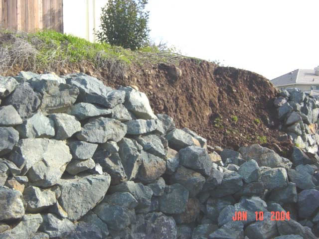
Figure 1. Photograph. Failure of non-engineered rockery in El Dorado Hills, California, 2004.
View larger version of Figure 1.
The objectives of this study are to review existing analytical methods and construction techniques currently in use and to develop a unified framework for design and specification of rockeries in modern highway construction. The ultimate goal of the project is to provide designers, inspectors, and contractors with a basis for evaluating existing rockeries and specifying and constructing new rockeries.
Based on review of available literature and the evaluation of several existing design procedures, the authors have developed a unified analysis and design framework that can be used in modern highway engineering. The framework is rational and follows recognized engineering principles derived from analysis procedures for gravity retaining walls.
Because rockeries are field assembled with natural and variable materials, careful field observation is essential to confirm that the as-built structures are consistent with the intent of the design. Therefore, guidelines have also been developed to provide designers, inspectors, and contractors with a basis for specifying, evaluating, and constructing rockeries.
Rockeries can be generally defined as rough rocks stacked in an "interlocking" pattern without concrete, mortar, or steel reinforcement. Neither mechanical nor physical connections are made between the individual rocks; "interlocking" is accomplished through proper rock layout, rock weight, and frictional interaction. Various terms have been used to describe rockeries, including "rock breast walls," "rockery walls," "dry-stack walls," "stone walls," and "rock walls." The terms used to describe rockeries often reflect the intended use, and, in some cases, preconceptions regarding rockeries.
There is some disagreement within the engineering community as to whether rockeries should be considered earth retaining structures. The City of Seattle, Washington, specifically states rockeries should not be used for earth retention purposes, (2) but can be used as an aesthetic treatment for an otherwise stable slope or to provide erosion protection (slope armor). The City of Seattle rockery guidelines appear to have been adopted by Mason County, Washington, and the City of Sparks, Nevada, both of which do not allow the use of rockeries for earth retention. (unpublished Internet references) On the other hand, municipalities such as the City of Brier, Washington, allow the use of rockeries as retaining structures, although they require engineered design for any rockeries over 0.9 m (3 ft) tall. (3)
Some researchers have acknowledged that rockeries can serve as retaining structures and have developed equations especially designed to evaluate the stability of rockeries retaining both native soils and fills. (4) (Dale C. Hemphill, unpublished) Others practitioners have taken the middle ground, conceding that while rockeries are best implemented as decorative architectural features or as slope protection for stable slopes, there is an increasing tendency to use rockeries for stabilization of oversteepened cut slopes or for retention of fill slopes. (5) Despite the different definitions and attitudes toward rockeries, they have been successfully designed and constructed to heights up to 7.6 m (25 ft) in the Pacific Northwest and northern California over the last decade.
For the purpose of this study, a rockery is defined as an engineered system of stacked angular rocks placed without mortar in an approximate "running bond" pattern. Rock dimensions are generally greater than 450 mm (18 in) and rock weights generally greater than 90 kg (200 lb). Stability of the system is achieved through the mass of the rocks and inter-rock friction. A rockery can further be defined as either protecting (i.e., it only supports itself and armors the underlying slope) or retaining (i.e., it supports itself and resists lateral earth pressures). The average thickness of protecting rockeries is generally less than retaining rockeries.
Rockeries are typically specified by their:
A diagram showing the rockery parameters defined above is presented as Figure 2.
Small landscaping walls comprised of cobble-sized rounded rocks can be often be found retaining 0.3 to 0.6 m (1 to 2 ft) of soil, often in garden or landscaping applications. These walls are typically not engineered and are often constructed mainly for aesthetic purposes; therefore, they are not considered rockeries for the purposes of this study.
For many years, it was common to describe the facing rocks used for rockery construction in terms of "man rocks." While the rockery design practice generally no longer uses this term for reasons described later in this report, many references and specifications still exist that refer to "man rocks". In general, a "man rock" is defined by the number of men it would take to manually move a rock into place using steel pry bars,(5) and, therefore, the term qualitatively describes the weight of a rock. For example, a "two-man rock" is defined as the largest rock two men could move into place; a "four-man rock" would require four men, and so on. Man rock sizes are generally capped at "six-man rocks."
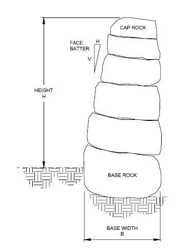
Figure 2. Graphic. Diagram showing definitions of height (H), base width (B), face batter, and relative rock sizes.
View larger version of Figure 2.
Because this unit of measure is subjective, definitions of man rock sizes often vary between municipalities, as shown in Table 1. Therefore, the classification of facing rocks into man rock groups in the field requires knowledge of the definitions being used. For example, Table 1 shows that while the maximum weight for a six-man rock is generally considered about 3,600 kg (8,000 lb), at least one classification system considers the typical weight to be 1,090 kg (2,400 lb). Similarly, while some of the municipalities use a range for typical man rock sizes, the City of Seattle uses a single number for 5- to 6-man rocks that appears to be an average size.
| Source | ||||||||||
|---|---|---|---|---|---|---|---|---|---|---|
| ARC (1) | City of Seattle, WA (2) | City of Brier, WA (3) | Gifford & Kirkland (5) | FHWA (6) | ||||||
| Rock Size (Man Rocks) | Weight, kg | Average Dimension, m | Weight, kg | Volume, m3 | Weight, kg | Diameter, m | Weight, kg | Surface Area/ Man Rock, m2 | Weight, kg | Average Dimension, m |
| 1 | 23 - 91 | 0.30 - 0.46 | 26 - 95 | 0.011 - 0.036 | 23 - 91 | 0.30 - 0.46 | 182 | 0.33 | 20 - 90 | 0.300 - 0.450 |
| 2 | 90 - 318 | 0.46 - 0.71 | 120 - 263 | 0.045 - 0.10 | 90 - 318 | 0.46 - 0.71 | 363 | 0.48 | 90 - 300 | 0.450 - 0.710 |
| 3 | 318 - 908 | 0.71 - 0.91 | 345 - 831 | 0.13 - 0.31 | 318 - 908 | 0.71 - 0.91 | 545 | 0.61 | 300 - 900 | 0.710 - 0.900 |
| 4 | 908 - 1,816 | 0.91 - 1.22 | 1,362 - 1,816 | 0.52 - 0.67 | 908 - 1,816 | 0.91 - 1.22 | 726 | 0.63 | 900 - 1,800 | 0.900 - 1.200 |
| 5 | 1,816 - 2,724 | 1.22 - 1.37 | 2,270 | 0.86 | 1,816
- 2,724 |
1.22 - 1.37 | 908 | 0.65 | 1,800 - 2,700 | 1.200 - 1.350 |
| 6 | 2,724 - 3,632 | 1.37 - 1.52 | 3,178 | 1.20 | 2,724
- 3,632 |
1.37 - 1.52 | 1,090 | 0.67 | 2,700 - 3,600 | 1.350 - 1.500 |
Stay up to date
Sign up for announcements on grant opportunities, training, and webinars.