Previous Chapter « Table of Contents » Next Chapter
FHWA-CFL/TD-06-006
November 2006
Federal Highway Administration
U.S. Department of Transportation
Central Federal Lands Highway Division 12300 West Dakota Avenue
Lakewood, CO 80228
Publication No. FHWA-CFL/TD-06-006
November 2006
Central Federal Lands Highway Division 12300 West Dakota Avenue
Lakewood, CO 80228
![]()
![]()
The Federal Lands Highway (FLH) of the Federal Highway Administration (FHWA) promotes development and deployment of applied research and technology applicable to solving transportation-related issues on Federal lands. The FLH provides technology delivery, innovative solutions, recommended best practices, and related information and knowledge sharing to Federal agencies, Tribal governments, and other offices within the FHWA.
The objective of this study is to review existing analytical methods and construction techniques currently in use for design and construction of rockeries and to develop a unified framework for design and specification of rockeries in modem highway construction. The ultimate goal of the project is to provide designers, inspectors, and contractors with a basis for evaluating existing rockeries and specifying and constructing new rockeries.

James W. Keeley, P.E., Director of Project Delivery
Federal Highway Administration
Central Federal Lands Highway Division
This document is disseminated under the sponsorship of the U.S. Department of Transportation in the interest of information exchange. The U.S. Government assumes no liability for the use of the information contained in this document. This report does not constitute a standard, specification, or regulation.
The U.S. Government does not endorse products or manufacturers. Trademarks or manufacturers' names appear in this report only because they are considered essential to the objective of the document.
The Federal Highway Administration (FHWA) provides high-quality information to serve Government, industry, and the public in a manner that promotes public understanding. Standards and policies are used to ensure and maximize the quality, objectivity, utility, and integrity of its information. FHWA periodically reviews quality issues and adjusts its programs and processes to ensure continuous quality improvement.
|
1. Report No. FHWA-CFL/TD-06-006 |
2. Government Accession No. | 3. Recipient's Catalog No. | ||||
|
4. Title and Subtitle
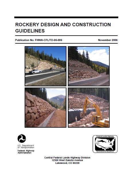
Rockery Design And Construction Guidelines |
5. Report Date November 2006 |
|||||
| 6. Performing Organization Code | ||||||
|
7. Author(s) Darren A. Mack, P.E., Steven H. Sanders, P.E., William L. Millhone, P.E., Renée L. Fippin, P.E., Drew G. Kennedy, P.G. |
8. Performing Organization Report No. | |||||
|
9. Performing Organization Name and Address Sanders & Associates Geostructural Engineering, Inc. (SAGE) 4180 Douglas Boulevard, Suite 100 Granite Bay, California 95746 |
10. Work Unit No. (TRAIS) | |||||
|
11. Contract or Grant No. DTFH68-05-P-00120 |
||||||
|
12. Sponsoring Agency Name and Address Federal Highway Administration Central Federal Lands Highway Division 12300 W. Dakota Avenue, Suite 210 Lakewood, CO 80228 |
13. Type of Report and Period Covered
Final Report April 2006 to November 2006 |
|||||
|
14. Sponsoring Agency Code HFTS-16.4 |
||||||
|
15. Supplementary Notes COTR: Khamis Haramy, FHWA-CFLHD; Advisory Panel Members: Scott Anderson, FHWA-FLH; Daniel Alzamora, FHWA-RC; Rich Barrows, FHWA-WFLHD; Khalid Mohamed, FHWA-EFLHD; and Roger Surdahl, FHWA-CFLHD. This project was funded under the FHWA Federal Lands Highway Technology Deployment Initiatives and Partnership Program (TDIPP). |
||||||
|
16. Abstract Rockeries consist of earth retaining and/or protection structures comprised of interlocking, dry-stacked rocks without mortar or steel reinforcement. They have been used for thousands of years and rely on the weight, size, and shape of individual rocks to provide overall stability. Some of the earliest rockeries constructed by the Federal Government date back to 1918. Within the private sector, commercially built rockeries have been constructed in the Pacific Northwest for at least the last four decades and in Northern California and Nevada for at least the last 10 years. As rockery design procedures tend to vary regionally, studies were performed to determine the methods by which rockeries are designed and constructed in various regions throughout the western United States. These design methods were then compared using several typical rockery design loading conditions to determine how the resulting rockery designs differ and which methods are most appropriate for a proposed design for the FHWA's FLH Divisions. Based on the research performed, a rational design methodology, which evaluates rockery stability as a function of the rockery geometry (height, base width, and batter), rock properties and placement, and lateral pressure imposed by the backfill materials, was developed. A sample design problem is included. Recommendations for specifying and constructing rockeries that are consistent with the design methodology are also provided. |
||||||
|
17. Key Words ROCKERY, ROCKERIES, EARTH RETENTION, ROCK WALLS, LATERAL EARTH PRESSURE, GEOPHYSICAL EVALUATION METHODS |
18. Distribution Statement No restriction. This document is available to the public from the sponsoring agency at the website https://www.cflhd.gov. |
|||||
|
19. Security Classif. (of this report) Unclassified |
20. Security Classif. (of this page) Unclassified |
21. No. of Pages 178 |
22. Price | |||
Form DOT F 1700.7 (8-72)
Reproduction of completed page authorized
| APPROXIMATE CONVERSIONS TO SI UNITS | ||||
|---|---|---|---|---|
| Symbol | When You Know | Multiply By | To Find | Symbol |
| LENGTH | ||||
| in | inches | 25.4 | millimeters | mm |
| ft | feet | 0.305 | meters | m |
| yd | yards | 0.914 | meters | m |
| mi | miles | 1.61 | kilometers | km |
| AREA | ||||
| in2 | square inches | 645.2 | square millimeters | mm2 |
| ft2 | square feet | 0.093 | square meters | m2 |
| yd2 | square yard | 0.836 | square meters | m2 |
| ac | acres | 0.405 | hectares | ha |
| mi2 | square miles | 2.59 | square kilometers | km2 |
| VOLUME | ||||
| fl oz | fluid ounces | 29.57 | milliliters | mL |
| gal | gallons | 3.785 | liters | L |
| ft3 | cubic feet | 0.028 | cubic meters | m3 |
| yd3 | cubic yards | 0.765 |
cubic meters
NOTE: volumes greater than 1000 L shall be shown in m3 |
m3 |
| MASS | ||||
| oz | ounces | 28.35 | grams | g |
| lb | pounds | 0.454 | kilograms | kg |
| T | short tons (2000 lb) | 0.907 | megagrams (or "metric ton") | Mg (or "t") |
| TEMPERATURE (exact degrees) | ||||
| °F | Fahrenheit | 5 (F-32)/9 or (F-32)/1.8 | Celsius | °C |
| ILLUMINATION | ||||
| fc | foot-candles | 10.76 | lux | lx |
| fl | foot-Lamberts | 3.426 | candela/m2 | cd/m2 |
| FORCE and PRESSURE or STRESS | ||||
| lbf | poundforce | 4.45 | newtons | N |
| lbf/in2 | poundforce per square inch | 6.89 | kilopascals | kPa |
| APPROXIMATE CONVERSIONS FROM SI UNITS | ||||
| Symbol | When You Know | Multiply By | To Find | Symbol |
| LENGTH | ||||
| mm | millimeters | 0.039 | inches | in |
| m | meters | 3.28 | feet | ft |
| m | meters | 1.09 | yards | yd |
| km | kilometers | 0.621 | miles | mi |
| AREA | ||||
| mm2 | square millimeters | 0.0016 | square inches | in2 |
| m2 | square meters | 10.764 | square feet | ft2 |
| m2 | square meters | 1.195 | square yards | yd2 |
| ha | hectares | 2.47 | acres | ac |
| km2 | square kilometers | 0.386 | square miles | mi2 |
| VOLUME | ||||
| mL | milliliters | 0.034 | fluid ounces | fl oz |
| L | liters | 0.264 | gallons | gal |
| m3 | cubic meters | 35.314 | cubic feet | ft3 |
| m3 | cubic meters | 1.307 | cubic yards | yd3 |
| MASS | ||||
| g | grams | 0.035 | ounces | oz |
| kg | kilograms | 2.202 | pounds | lb |
| Mg (or "t") | megagrams (or "metric ton") | 1.103 | short tons (2000 lb) | T |
| TEMPERATURE (exact degrees) | ||||
| °C | Celsius | 1.8C+32 | Fahrenheit | °F |
| ILLUMINATION | ||||
| lx | lux | 0.0929 | foot-candles | fc |
| cd/m2 | candela/m2 | 0.2919 | foot-Lamberts | fl |
| FORCE and PRESSURE or STRESS | ||||
| N | newtons | 0.225 | poundforce | lbf |
| kPa | kilopascals | 0.145 | poundforce per square inch | lbf/in2 |
*SI is the symbol for the International System of Units. Appropriate rounding should be made to comply with Section 4 of ASTM E380. (Revised March 2003)
A - Acceleration Coefficient per AASHTO Division I-A, Section 3
A* - Amplified peak acceleration
Aa, Av - Acceleration coefficients per ATC-3-06
AASHTO - American Association of State Highway Transportation Officials
A.D. - Latin, Anno Domini, current calendar epoch
AOS - Apparent Opening Size
apeak - Peak spectral acceleration, gravity (g)
ARC - Associated Rockery Contractors
ASTM - American Society of Testing and Materials
ATC - Applied Technology Council
B - Base rock width, m
BMP - "Best Management Practices" as related to site erosion, sediment, and runoff control and reduction
c, c' - Total and effective soil cohesion values, respectively, in kPa. Although effective stresses are most typically used, the term "c" is commonly used throughout this report.
ca. - Latin, circa, meaning "about" for dates that are approximately known
CalTrans - State of California, Department of Transportation
cF, c'F - Total and effective soil cohesion values in the foundation soil, in kPa
CFLHD - Central Federal Lands Highway Division
CIE - Seismic inertial coefficient
CO - Contracting Officer
d - Depth of soil to neglect when computing passive resisting force, μ dpeak - Peak spectral displacement, cm
Dpeak - Embedment depth at toe of rockery, m
D* - Amplified peak displacement
e - Moment eccentricity relative to center of base rock, m
es - Moment eccentricity relative to center of base rock due to seismic forces, m
EFP - Equivalent fluid pressure applied by soil, kN/m3
EPA - Effective peak acceleration, g
EPV - Effective peak velocity, cm/s
FA - Active earth pressure force acting on the back of the rockery
FA,H - Horizontal component of active earth pressure force kN (per meter of rockery)
FA,V - Vertical component of active earth pressure force, kN (per meter of rockery)
FAE - Total static plus seismic thrust acting on rockery, kN (per meter of rockery)
ΔFAE - Incremental seismic thrust acting on rockery, kN (per meter of rockery)
FH - Sum of static horizontal driving forces acting on rockery, kN (per meter of rockery)
FH,S - Sum of static and seismic horizontal driving forces acting on rockery, kN (per meter of rockery)
FHWA - Federal Highway Administration
FLH - Federal Lands Highway
Foundation Fill - Material conforming to Section 704.01 of the FHWA Standard Specifications (FP-03)
Fp - Passive resisting force on toe of rockery, kN (per meter of rockery)
Fs - Horizontal resultant force due to application of vertical surcharge load, kN (per meter of rockery)
Fμ - Static resisting friction force of bottom of base rock, kN (per meter of rockery)
Fμ,S - Static and seismic resisting friction force of bottom of base rock, kN (per meter of rockery)
FS - Factor of safety
FSBC - Factor of safety with respect to bearing capacity
FSOT - Factor of safety with respect to external overturning
FSOT_INT - Factor of safety with respect to internal (inter-rock) overturning
FSseismic - Factor of safety with respect to required rockery weight to limit rockery displacement to Δ or less
FSSL - Factor of safety with respect to base sliding
GPR - Ground penetrating radar, a type of geophysical evaluation method
H - Rockery height, m
H/B - Height-to-base-width ratio
HDPE - High density polyethylene, usually referring to a type of plastic pipe
HEC - Hydraulic Engineering Circular
HP - Ultraseismic Horizontal Profiling Method, a type of geophysical surface wave method
i - Slope inclination, measured up from horizontal, per A. J. Hendron, Jr., methodology
IR - Impulse Response, a type of geophysical surface wave method
KA - Coefficient of active earth pressure
KAE - Lateral earth coefficient for computation of static plus seismic thrust force
kh - Horizontal seismic coefficient
Kp - Coefficient of passive earth pressure
kv - Vertical seismic coefficient
LTDS - Long term design strength of geogrid reinforcement
MARV - Minimum Average Roll Values
Mo - External overturning moment about toe of rockery imposed by lateral earth pressure (horizontal component) and surcharge loads, kN - μ (per meter of rockery)
Mo,s - External overturning moment due to static and seismic loads, kN - μ (per meter of rockery)
Mo_int - Internal (inter-rock) overturning moment about toe of intermediate rock imposed by lateral earth pressure (horizontal component) and surcharge loads, kN - μ (per meter of rockery)
Mr - External resisting moment about toe of rockery imposed by rockery weight, lateral earth pressure (vertical component), and passive pressure, kN - μ (per meter of rockery)
Mr,s - External resisting moment about toe of rockery imposed by rockery weight and vertical components of static and seismic lateral earth pressures kN - μ (per meter of rockery)
Mr_int - Internal resisting moment about toe of intermediate rock imposed by partial rockery weight, lateral earth pressure (vertical component), and passive pressure, kN - μ (per meter of rockery)
MSE - Mechanically stabilized earth or embankment
OSHA - Occupational Safety and Health Administration
PCR - Poorly constructed rockery as defined by A. J. Hendron, Jr.
PGA - Peak ground acceleration, g
PS - Parallel Seismic, a type of geophysical cross-hole logging method
PVC - Polyvinyl chloride, a type of plastic pipe
qmax - Maximum applied bearing pressure at toe of base rock due to moment eccentricity, kPa
qmax,s - Maximum applied bearing pressure at toe of base rock due to moment eccentricity under seismic loading, kPa
qs - Vertical surcharge pressure acting on the ground surface behind the rockery, kPa
RSP - Rock slope protection, e.g., riprap
RSS - Reinforced soil slope
SAGE - Sanders & Associates Geostructural Engineering, Inc.
SE - Sonic Echo, a type of geophysical surface wave method
Ta - Allowable tensile strength for geotextile soil reinforcement, equal to LTDS/FS
UBC - Uniform Building Code
U.S. - United States
UV - Ultraviolet light, such as sunlight
vpeak - Peak spectral velocity, cm/sec
V* - Amplified peak velocity
W - Total weight of rockery (unit width basis), kg
WCR - Well-constructed rockery as defined by A. J. Hendron, Jr.
Wi - Weight of rockery component (unit width basis), kg
xi - Moment arm from toe of rockery to centroid of mass for rockery component, m
z - Point of application of FAE, measured vertically from base of rockery, m
Δ - Tolerable rockery displacement for Richards and Elms analysis, in
ΔFAE - Incremental seismic thrust acting on rockery, kN (per meter of rockery)
α - Angle, measured up from the horizontal, to the back cut or rear face of rockery, degrees. Positive angle is defined as face of back cut sloping up and away from the base of the rockery, starting from the bottom of the cut.
αA, αV, αD - Newmark and Hall amplification factors
β - Retained ground surface inclination ("backslope"), degrees. Positive angle if slope increases in height with increasing distance from the back of the rockery.
δ - Interface friction angle between retained soil and back of rockery/crushed rock backfill zone, degrees
φ, φ' - Total and effective soil friction angle / angle of internal friction, respectively. Although effective stresses are most typically used, the term "f" is commonly used throughout this report.
φCR - Friction angle (effective or total) of crushed rock backfill
φF - Friction angle (effective or total) of foundation soil and soil at toe of rockery
γ, γs - Density of retained soil, kN/m3
γCR - Density of crushed rock backfill (net density, including voids), kN/m3
γR - Density of rockery facing (net density, including voids), kN/m3
γF - Density of foundation soil, kN/m3
μ - Friction factor for sliding
ψ - Back cut inclination, degrees
Stay up to date
Sign up for announcements on grant opportunities, training, and webinars.