Publications
Rockery Design and Construction Guidelines
Previous Chapter « Table of Contents » Next Chapter
CHAPTER 6 - CONSTRUCTION INSPECTION GUIDELINES
Like most engineered structures, careful observation is required during rockery construction to check that the as-built structure conforms to the design intent, plans, and specifications. As for any retaining structure, geotechnical and structural inspections should be performed. The types of items to be checked during each type of inspection include:
Geotechnical
- The foundation subgrade should be checked to verify a firm bearing layer capable of supporting the rockery is present.
- The back cut should be checked to confirm that the retained soils are consistent with the soil conditions assumed during design.
Structural
- The items discussed in Chapter 5, including base rock width, maximum height, rock bearing, chinking, etcetera.
- The drainage system (drain pipes and drainage material) should be checked to confirm the proper materials and gradients were used and that all pipes are connected to appropriate drainage outlets.
These items have been summarized in the attached checklists and sample field inspection forms presented at the end of this chapter. Separate forms are provided for projects in which a single rockery is observed at the site and for when multiple rockeries, at different locations, are observed across the same jobsite.
For each rockery over 1800 mm (6 ft) in height, or where significant surcharges are retained, at least four inspections should be performed by a Geotechnical Engineer or qualified Soils Technician/Inspector to observe rockery construction. For rockeries more than 33 m (100 ft) long, at least one additional inspection should be performed for each additional 33 m segment of rockery face.
Construction inspection should be performed, as a minimum, during the three key stages of construction, defined as follows:
- Initial Inspection: Observe excavation dimensions prior to base rock placement, drainage pipe and filter fabric placement, and base rock width.
- Mid-Construction Inspection: Observe rock placement, size, and batter of rockery face, placement of crushed rock drainage material, and layout of drainage outlets.
- End of Rockery Construction Inspection (contractor preparing to leave site): Observe overall rock placement for completed rockery, including chinking; confirm that exposed drainage outlets will be directed to a suitable outlet; check cap rock placement and size, and determine if grouting is required; and confirm final height is consistent with project plans. At this time, observed defects in rockery construction should be fixed while the contractor is still on-site.
The final inspection should be preformed at the completion of all rockery construction and grading above and below the rockeries. The purpose of this visit is to:
- Observe final grading above and below rockery.
- Confirm the final exposed height.
- Confirm drainage outlets have been tied into a suitable collection device or otherwise properly outlet.
- Check that facing rocks or cap rocks have not been disturbed by any grading after the completion of rockery construction.
The actual number of inspections required for each project will depend on the contractor's schedule, the different stages of rockery construction that may be observed in the same visit, and the number of rockeries being constructed simultaneously. More frequent observation should be performed if difficult or unusual construction conditions are expected.
ROCKERY INSPECTION CHECKLIST
Initial Inspection (After Excavation)
Geotechnical
- The foundation subgrade consists of firm, undisturbed soil or rock and is consistent with the subgrade material identified on the project plans. Where weak or disturbed soil was present, it has been recompacted or overexcavated and replaced. (Do not deepen foundation without approval of the Design Engineer or Geotechnical Engineer.)
- Adverse (out-of-slope) bedding, jointing, or foliation was/was not (circle one) observed. Where adverse bedding was observed, the Geotechnical Engineer was notified.
Structural
- The minimum base rock width, B, per the project plans is 0. _________H.
- The excavation width is equal to the design base rock width, B, plus 300 mm (12 in), as a minimum, to accommodate the drainage blanket.
- The excavation is level or sloped toward the back of the rockery.
- The excavation depth provides for a minimum of 300 mm (12 in) of embedment and at least 1800 mm (6 ft) of lateral cover. Both criteria are met concurrently.
- Project plans do/do not (circle one) show additional requirements for scour or frost heave. Where present, these requirements have been met.
- For rockeries constructed perpendicular to slopes, the foundation excavation is sloped for inclinations 1V:2H or less. Foundation steps have been used where the excavation is sloped steeper than 1V:2H. Leveling gravel has been used where necessary.
- The back cut conforms to the minimum batter shown on the project plans.
- Base rocks are hard, angular, and durable, e.g., they ring when struck with a hammer. They are roughly rectangular, tabular, or cubic in shape. They are free of cracks, fissures, foliation, or other planes of weakness, particularly where they are subject to significant freeze-thaw cycles.
- The base rocks generally conform to the minimum width, B, and no rock widths are less than β minus 150 mm (6 in). No two consecutive rocks have a width less than B.
- Where B exceeds 1700 mm, two rocks may comprise the base rock. Where this occurs, the rocks are in contact in at least two (2) locations.
- Base rocks are inclined back into the slope at least 5%.
ROCKERY INSPECTION CHECKLIST
Mid-Construction Inspection
- Facing rocks are hard, angular, and durable, e.g., they ring when hit with a hammer. They are roughly rectangular, tabular, or cubic in shape. They are free of cracks, fissures, foliation, or other planes of weakness, particularly where they are subject to significant freeze-thaw cycles.
- Facing rocks are inclined back into the slope at least 5%.
- Each facing rock is in contact with at least two rocks below it. Each rock has at least three (3) bearing points total - two (2) in front, one (1) in back.
- The first contact point between an upper rock and a lower rock is located within 150 mm (6 in) of the face of the rockery.
- The backs of the rocks are aligned along an imaginary vertical plane.
- There are no "columns" of rocks; i.e., no continuous vertical seams.
- There are no continuous horizontal planes in the rockery.
- The maximum face batter is between 4V:1H and 6V:1H or otherwise conforms to the project plans.
- Non-woven, Type I-B geotextile has been placed over the back cut prior to placement of crushed rock backdrain.
- Drain pipes and crushed rock backdrain installation is per the project plans. Suitable outlets have been identified on the project plans. Drain pipes have/have not (circle one) been connected.
ROCKERY INSPECTION CHECKLIST
End of Rockery Construction Inspection
Geotechnical
- All rockery backfill has been placed, moisture conditioned, and compacted in accordance with the project plans and specifications and the Geotechnical Engineer's recommendations.
Structural
- All voids greater than 150 mm (6 in) are chinked.
- Chink rocks, where present, cannot be removed by hand.
- There is no rock spalling or soil piping through the voids in the face of the rockery.
- Cap rocks weigh at least 90 kg (200 lb). There are no loose cap rocks or rocks that can otherwise be moved by hand. Small cap rocks have been removed or grouted in place.
- The maximum height (total and exposed) of the rockery conforms to the project plans.
- Surface drainage has been directed away from the rockery or a concrete v-ditch or impermeable soil swale has been constructed above the rockery.
ROCKERY INSPECTION CHECKLIST
Final Inspection
- Final grading above and below the rockery conforms to the rockery plans and is consistent with the grading plans.
- Exposed or total height at the completion of grading is consistent with the design height shown on the project plans.
- Drainage pipes are connected to a suitable outlet. If buried, obtain confirmation that pipes were properly connected.
- Neither facing nor cap rocks have been disturbed by grading operations after the completion of rockery construction.
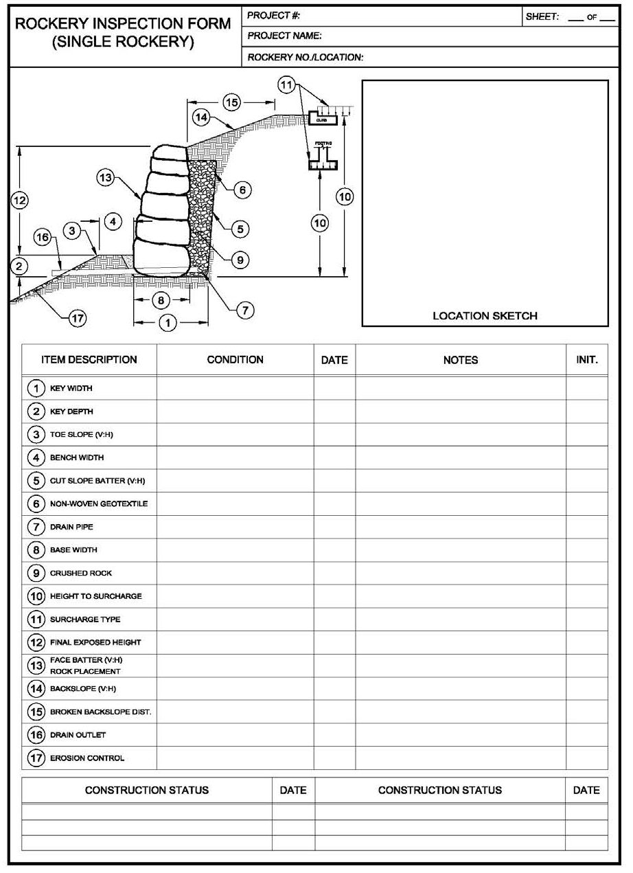
View larger version of Single Rockery form.
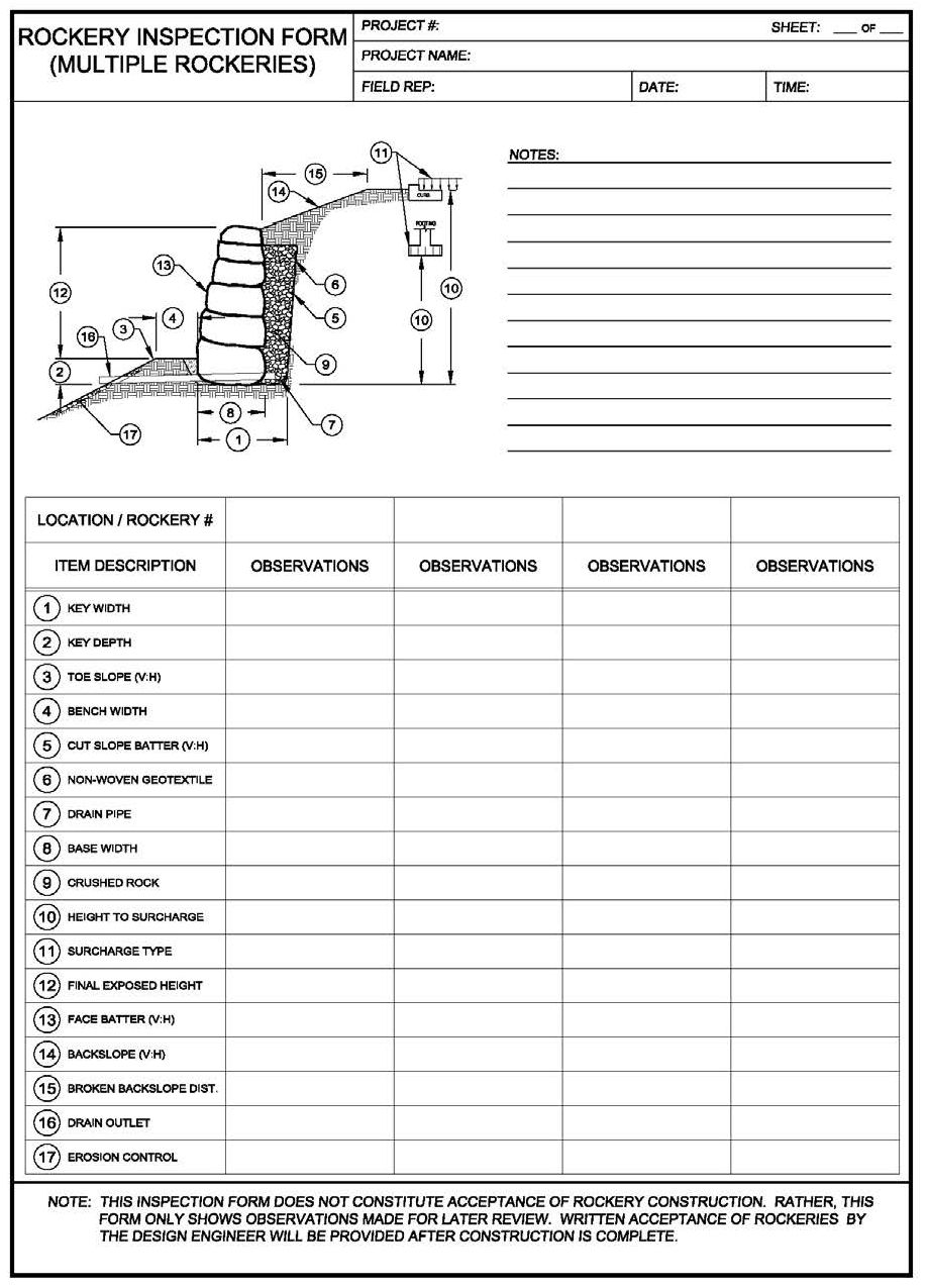
View larger version of Multiple Rockeries form.
Previous Chapter « Table of Contents » Next Chapter