Previous Chapter « Table of Contents » Next Chapter
Rockeries have been used in roadside and highway applications in the United States since the early 1900s. Therefore, it is likely that existing, historic rockeries will be encountered that support existing roadways. Recently, evaluation of existing rockeries was required for El Portal Road in Yosemite National Park (California) and for Trail Ridge Road in Rocky Mountain National Park (Colorado). It is likely the FLH or other transportation agencies will be required to evaluate the suitability of other aging rockeries for continued use in the near future. This chapter presents methods to evaluate the stability of existing historic rockeries.
To analyze the stability of existing rockeries, information regarding the rockery geometry and retained soil properties must be determined. The most important properties affecting rockery stability are:
The rockery height and batter are relatively easy and straightforward to measure in the field. The rockery base width is more difficult to determine, as discussed in the following subsection. Determination of strength parameters for the retained soil is discussed later in this chapter.
The parameters H, β, B, and φ are most critical with regard to overall rockery acceptability and gross stability. However, to determine if bulging, inter-rock sliding, and inter-rock overturning resistances are acceptable, additional field observations are required. The rockery face should be carefully evaluated to check that the following criteria are satisfied:
For roadside applications, it is also important to note any surcharges acting on the existing rockeries. Surcharges can include a traffic surcharge pressure, sloping backfill above the rockery, and embedded posts for guardrails or fences.
Figure 74 shows an example of a well-constructed rockery. The rocks all bear on at least two lower rocks, the rockery is properly chinked, there are no vertical seams, and the contact points are all at the front of the rockery. Figures 75 and 76 show examples of improperly constructed rockeries with either vertical stacks of rocks and/or rocks tilted out of the face of the rockery.
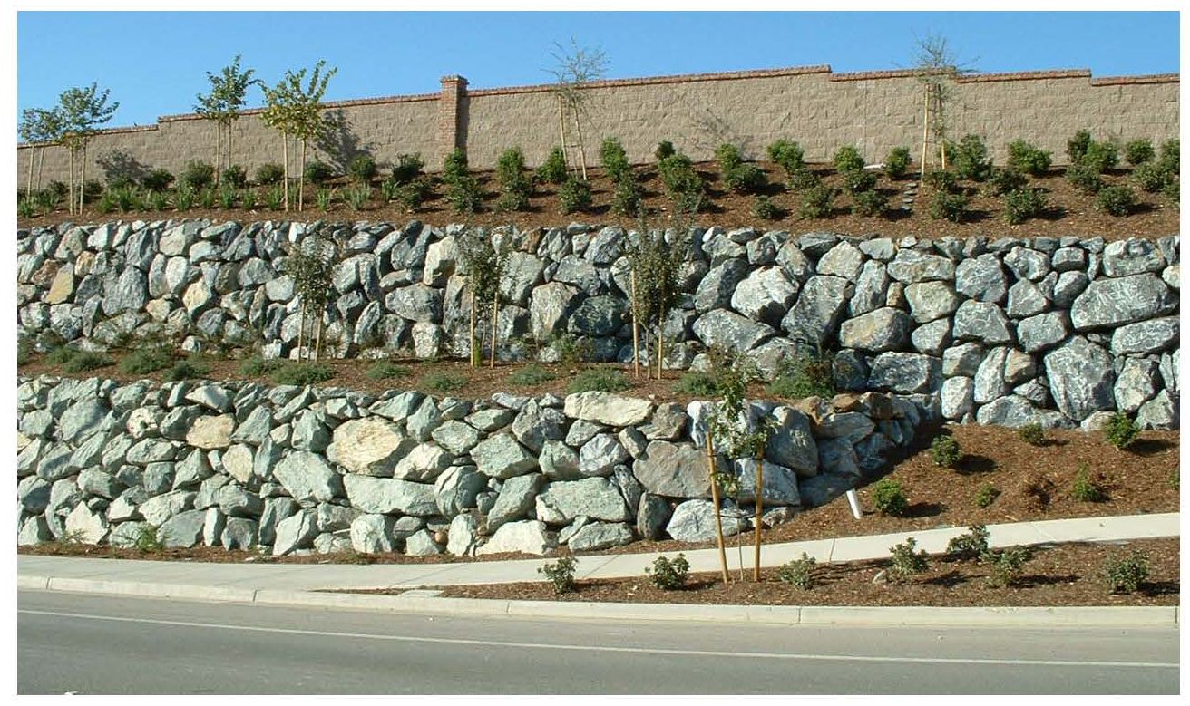
Figure 74. Photograph. Example of proper layout, interlock, and chinking of variable shape and size rocks.
View larger version of Figure 74.
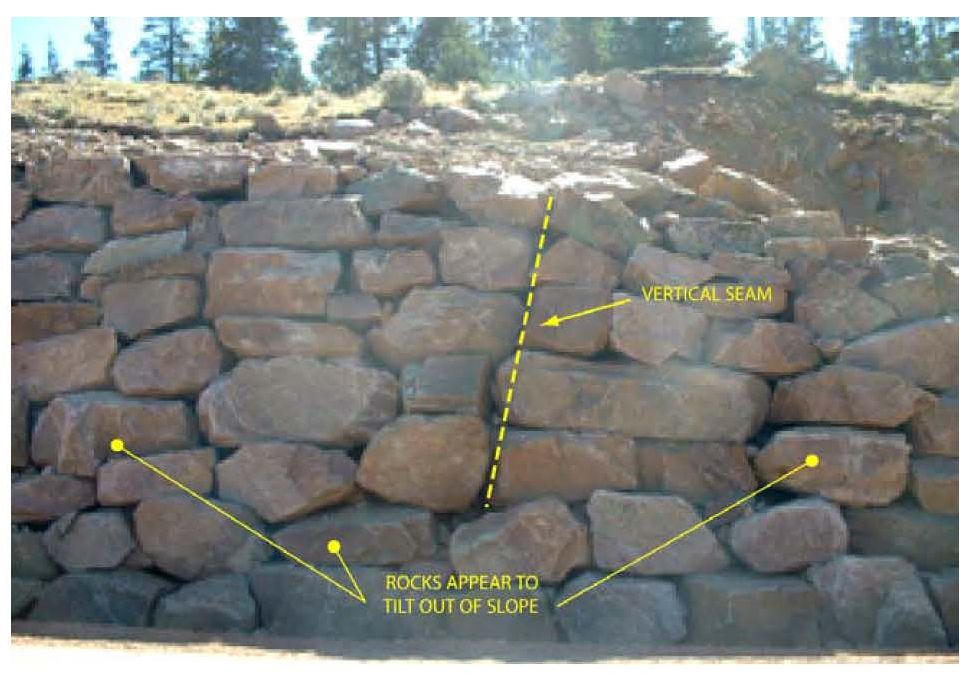
Figure 75. Photograph. Example of improper rockery layout evidences by vertical seams and rocks inclined out of face.
View larger version of Figure 75.
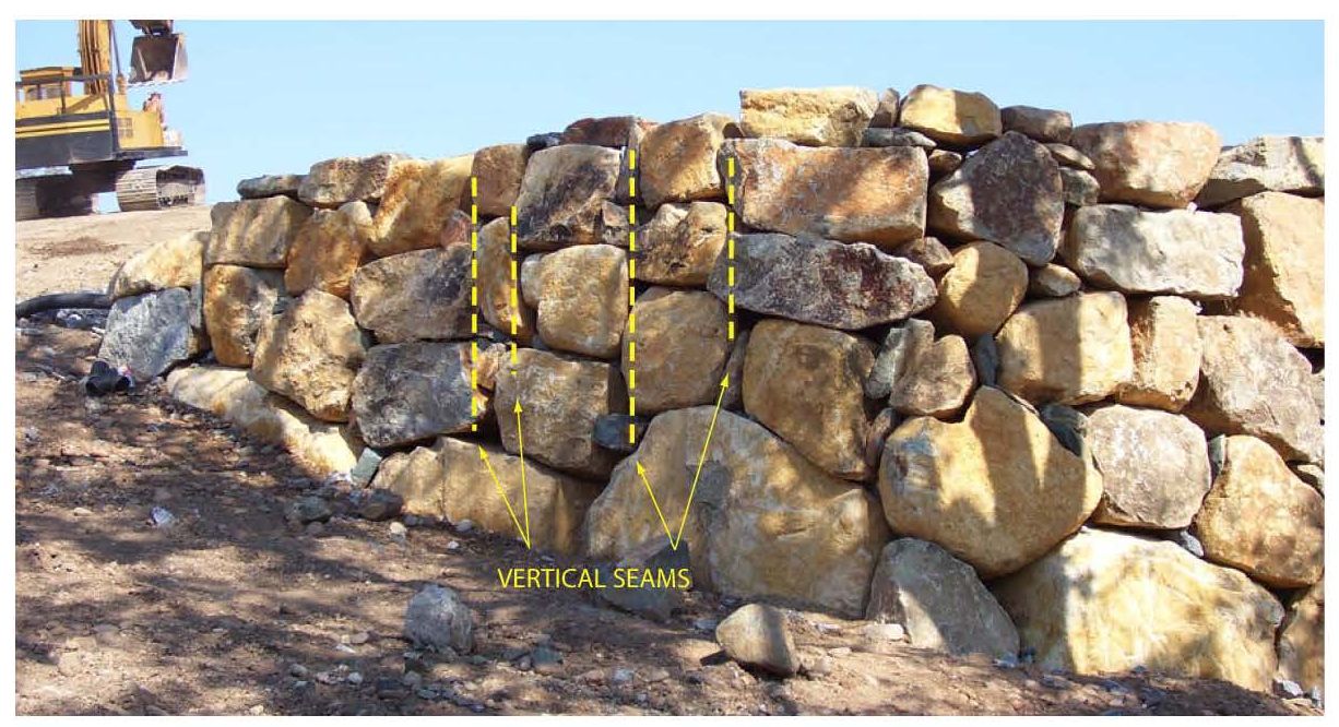
Figure 76. Photograph. Example of improper rockery layout evidenced by several vertical seams.
View larger version of Figure 76.
Because of the presence of voids within the rockery face, it is unlikely that hydrostatic water pressure could build up behind an existing rockery and cause a failure. However, seepage from behind the rockery could wash soil through the face by piping or erosion. Erosion of soil through the rockery could cause settlement behind the rockery due to the resultant ground loss.
To prevent erosion through the rockery, the rockeries should have granular backdrains. The backdrains should discharge to a suitable outlet and be properly graded (or wrapped in a non- woven geotextile) to prevent soil migration from the retained soil into the drainage material. This granular backfill also helps to reduce the lateral earth pressures on the rockery, and, therefore, increases the overall stability. For that reason, the rockery should be inspected to as part of the evaluation to determine if granular material can be observed behind the facing rocks and the presence or absence should be noted in the observation notes. If drain pipes or outlets are observed, they should also be noted.
When performing the field evaluation, temporary stationing should be set along the top of the rockery and observations of the items discussed previously made at regular intervals. The values can be recorded in either tabular or graphical form relative to the temporary stationing. A copy of the construction observation checklist presented in Chapter 6 can also be used at each cross- section location (station) to check the observed construction relative to current standards.
The rockery base width, B, may be the most difficult parameter to measure in the field. Base rocks are typically embedded partially below grade, and the tops and backs of base rocks are obscured by overlying facing rocks. One method that can be used to directly measure the base rock width is to deconstruct a portion of the rockery and physically measure the base rocks.
While this provides the most accurate measurement of base width, it only provides dimensions at a limited number of points along the rockery; that is, it doesn't necessarily capture variations along the structure. In addition, it is likely that partial deconstruction of an existing rockery is infeasible in most roadside applications without significant disruption to the existing roadway. It may also be unacceptable to deconstruct a historically significant rockery.
Another method that can be used consists of searching for sizable voids between rocks near the base of the rockery and estimating the base rock width with a tape measure. In general, a void at least 50 mm (2 in) in diameter at the face of the rockery is required for this method to be feasible. Furthermore, the rocks must interlock in such a way that the void used to estimate the width extends to the rear of the rockery. Because this process is highly dependent on the rock configuration, layout, and access for each rockery, the feasibility will vary on a case-by-case basis. Nevertheless, while this method will always result in some uncertainty regarding the actual base rock width, any inaccuracies will tend to be conservative as the estimated base rock widths will be equal to or less than the actual width.
If physical measurements cannot be obtained, estimates of base rock width may need to be obtained using nondestructive geophysical methods. Geophysical methods generally consist of using vibrations, seismic waves, or radio waves (radar) to evaluate subsurface conditions. These methods generally rely on reflections caused by different material properties, especially density, to determine where transitions between materials occur. In the case of rockeries, they could be used to evaluate the difference in material properties between the facing rocks and the retained soil. While geophysical measurement methods are feasible conceptually, the work performed for this study suggests application of these methods has been very limited with respect to rockery evaluation.
Based on review of the FHWA publication Application of Geophysical Methods to Highway Related Problems,(23) three types of geophysical methods appear feasible for estimation of rockery dimensions in the field - surface waves, ground penetrating radar, and cross-hole logging methods. The methods are discussed in the following sections.
Surface Waves:
Surface wave methods include methods such as Sonic Echo (SE), Impulse Response (IR), and the Ultraseismic Horizontal Profiling Method (HP). These methods generally involve generation of a surface wave by imparting a strong shock to the face of the structure being tested and measuring wave reflection using sensitive vibration-monitoring devises, such as geophones or accelerometers. The impact is usually generated using an instrumented sledgehammer or a mallet.
Surface wave techniques such as SE and IR have traditionally been used for vertical applications and may not be applicable to horizontal measurements. However, the HP method shows more promise in this regard as it has specifically been developed for horizontal applications such as bridge abutment evaluation. Unfortunately, a case history regarding the use of HP to estimate the thickness of a rockery could not be identified during this study. Surface wave methods are also limited by the sensitivity of the geophones and accelerometers to background vibrations, and, therefore, the methods would be difficult to implement where background vibrations are high, such as along high-traffic roads, especially highways.
The refractive seismic method, another surface wave method, was used for rockery evaluation with some success on the Apache Trail (SR 88) in Arizona in 2001. (Dennis Duffy, 2001) For this application, geophones were attached to the face of an existing rockery and rock accelerations induced by passing traffic were measured. While this data did not provide information relative to base rock widths, it was used to evaluate overall rockery stability and sensitivity to traffic loads passing above the rockery.
Ground Penetrating Radar:
Ground Penetrating Radar (GPR) uses electromagnetic waves to evaluate subsurface conditions and is often used to determine the thickness of concrete, masonry, or timber structures. It can also be used to identify density contrasts beneath the soil, such as underground utilities or voids. The primary application for the evaluation of rockeries would be to estimate the thickness of the rockery by identifying the rear of the facing rocks. To accomplish this goal, it would be necessary to perform a GPR survey line immediately behind the top of the rockery and look for a density contrast between the facing rocks and retained soil, or from reflections off the back of the rocks. Horizontal GPR may also provide valuable information regarding rockery thickness.
Cross-Hole Logging Methods:
Cross-hole logging consists of drilling a vertical bore hole within 1.5 m (5 ft) of the back of the rockery and installing hydrophones or three-component geophones in the bore hole. In the case of the Parallel Seismic (PS) method, the waves are generated on the face of the structure and detected within the bore hole by the hydrophones. For the Borehole Radar method, the waves consist of electromagnetic (radar) waves. Information regarding the use of either of these methods for rockery evaluation could not be located as part of this study.
Summary:
This study found that geophysical methods have only been used sparingly for the evaluation of rockeries. Many of these methods were developed for, and work best on, continuous masses, such as concrete structures or concrete and steel foundations. Because rockery facing rocks have joints and seams and may only contact each other at discrete points, they are relatively discontinuous. Therefore, they may not transmit or reflect the seismic or electromagnetic waves in an effective manner and the results may be difficult to interpret.
Another potential drawback to geophysical methods is that they are most effective when the adjacent, dissimilar materials being studied have a relatively high density contrast, which is usually represented by differences in shear wave velocity. Two example materials with much different shear wave velocities are soil and concrete. However, where rockeries are constructed with gravel or crushed rock backdrains, the shear wave velocity contrast between the facing rocks and crushed rock may not be sufficient to differentiate the two. In this case, it is possible the geophysical methods could yield a base rock width greater than what is actually present. Depending on the other assumptions made, this could result in an unconservative stability evaluation. The lack of contrast could also be a concern where rockeries retain very dense soil or bedrock.
Because of the uncertainties involved and the apparent scarcity of case histories, the application of geophysical methods to evaluate existing rockeries appears to be an area where future study should be focused.
Just like new construction, the strength parameters for the soil or rock retained behind an existing rockery has a significant impact on the performance and acceptability of the rockery. Wherever existing rockeries are to be evaluated, a geotechnical and/or geologic investigation should be performed to evaluate the retained materials. The scope of the investigation should be appropriate for the height and length of the rockery being evaluated and the potential consequences should future instability occur. A typical investigation could involve excavation of test pits, drilling of soil borings, and/or geologic mapping. As a minimum, a properly performed investigation should identify:
Once the soil, surcharge, and rockery parameters have been collected, this data should then be used to evaluate the existing rockery. In the case of rockeries that are less than 1800 mm (6 ft) tall, the use of prescriptive standards, such as those published by the City of Seattle, (2) may be a sufficient screening tool. Caution is urged in using prescriptive methods for rockeries subject to surcharge loads, especially traffic, as most of the prescriptive methods specifically exclude the application of surcharge loads.
Another relatively simple screening tool is to compare the rockery geometry to the chart developed by Hendron,(5) as shown in Figure 9, for poorly constructed rockeries (PCRs). This chart provides a check that the actual height-to-base-width (H/B) ratio is below the critical ratio for the measured values of H, B, and α. However, while this check provides a method to determine if the H/B ratio is above the critical value, it doesn't provide an actual factor of safety to aid in the evaluation. For instance, an H/B ratio that is twice the critical value may not translate into a FSOT of 2. It should also be noted that the Hendron chart was developed assuming specific soil and rock properties, and, therefore, may not be applicable for all soil conditions encountered. As with the prescriptive design methods, this chart does not include an allowance for surcharge pressures.
As an alternative, equations developed by Gray & Sotir, as shown in Figures 16 and 17, can be used to generate site-specific charts utilizing the physical and geometric properties of the rockery and retained soil. The type of screening performed using these equations depends on the factor of safety (FS) selected. Using an overturning factor of safety (FSOT) of 1.0 would generate a chart that would allow for screening of rockeries that are inadequate and/or require "immediate" replacement; that is, their H/B ratios are less than the critical value. The results from this analysis should be very similar to those discussed previously for the Hendron chart. Use of a higher FS, however, might allow for identification of rockery segments that are acceptable without further evaluation. Caution should still be used with this chart, as surcharge pressures are not included.
The screening methods described above are adequate to determine if existing rockeries are inherently stable or if further evaluation is required. Where additional evaluation is require, or if heavy surcharge pressures act on the rockeries, the analysis procedures discussed in Chapter 4 of this report should be used to check that the rockeries have adequate factor of safety.
As part of this study, a technical paper was reviewed that discussed the of numerical modeling techniques to the evaluation of rockeries. The proposed method includes the use of Particle Flow Code (PFC) and the Discrete Element Method (DEM) to dynamically model the interactions between individual rocks. (Rock, 2006, unpublished) Rock interactions are modeled using a spring- dashpot constitutive model for normal contact and a Coulomb friction model for shear forces. The individual rocks are modeled as rigid bodies with discrete points of contact. If the factors of safety are low enough, the model uses the equations of motion to estimate movement/failure of the rockery and the final rockery configuration, if applicable.
Review of numerical modeling techniques was not a primary goal of this study, and therefore, the approach described above was not investigated in detail. In general, numerical analysis methods show promise for the evaluation of specific rockery conditions where rockery performance is critical and the soil strength parameters, rockery geometry (including individual rock sizes), and loading conditions are all clearly defined. However, the irregular nature of rockeries and heterogeneous nature of retained soil is such that determination of this level of detail is expected to be difficult under most circumstances. As a result, numerical evaluation of many cross sections for one wall is not likely to be justified, as the determination of the individual rock sizes is expected to be difficult and time consuming. The feasibility of numerical modeling techniques for rockery evaluation is recommended for future study.
Stay up to date
Sign up for announcements on grant opportunities, training, and webinars.