Previous Chapter « Table of Contents » Next Chapter
For most civil works, the performance of a structure is directly related to the quality of construction. For a rockery, this concept is magnified several times by the fact that rockeries are constructed from irregularly shaped, naturally occurring materials. Unlike timber, steel or concrete retaining structures, for which the construction material properties are relatively well- defined and well-controlled, rockeries are constructed of variably shaped rocks, no two of which are identical. Therefore, the skill of the contractor constructing the rockery has a large impact on the overall performance, including:
As a result, careful observation during construction and quality control procedures are required to verify that the rockery is constructed per the plans and specifications, and that the actual ground conditions encountered are consistent with the design assumptions.
Where rockeries are constructed, cuts generally consist of excavation of the base rock subgrade (foundation) and the back cut. In native cut situations, the back cut will be made in native soil or bedrock. For fill situations, the back cut will consist of engineered fill. To ensure that the back cut is within adequately compacted engineered fill, the fill should generally be overbuilt several feet prior to rockery construction and then trimmed back to the desired back cut location.
In some instances, the site conditions are such that it is more practical to place the retained fill concurrently with the facing rocks. One such example would be a site with a slope below the toe of the rockery. When the fill and rockery are constructed concurrently, the width of the gravel drainage layer should be increased to 600 mm (24 in) because of the difficulty in obtaining adequate compaction at the outer face of the fill.
The foundation excavation should be sufficiently wide to permit placement of the specified leveling course. The leveling course can consist of at least 300 mm (12 in) of crushed, screened, 100- to 150-mm (4- to 6-in) backdrain rock. Alternatively, the leveling pad can consist of Foundation Fill meeting the requirements of the Standard Specifications for Construction of Roads and Bridges on Federal Highway Projects (FP-03), Metric Units, U.S. Department of Transportation, Federal Highway Administration, Federal Lands Highway, Section 704.01, Foundation Fill. The base of the excavation should be level or inclined back slightly (on the order of 5%) into the slope, as shown in Figure 55. The foundation excavation should never slope forward towards the face of the rockery, as this could lead to rockery instability.
The depth of the foundation excavation will vary depending on the conditions at the toe of the rockery. For level toe conditions, nominal embedment of 300 mm (12 in) is generally sufficient unless frost considerations apply, in which case the rockery should be founded below the zone of frost heave. For sloping toe conditions, the embedment should be such that at least 1800 mm (6 ft) of soil is present horizontally in front of the rockery. This requirement provides protection against shallow erosion or other disturbances that could remove the soil at the toe of the rockery or possibly undermine the rockery. An example of the necessary cover at the toe of the rockery is shown in Figure 55. The Geotechnical Engineer should perform a slope stability analysis, particularly where toe conditions are steeper than 1V:2H, to check that the slope below the rockery, as well as the over overall rockery system, has an acceptable factor of safety.
The minimum embedments discussed previously are prescriptive values, and larger values may be required to satisfy other engineering requirements, such as bearing capacity, global stability, scour, or frost heave. For example, where scour is a concern, the rockery should be founded at least 0.6 m (2 ft) below the estimated scour depth. In addition, the base rocks for such a rockery should be sized for a total height equal to the planned exposed height plus the estimated scour depth.
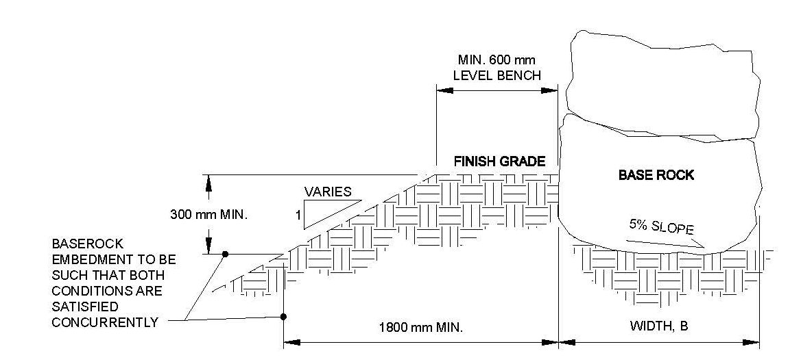
Figure 55. Graphic. Minimum embedment required for a sloping toe condition.
View larger version of Figure 55.
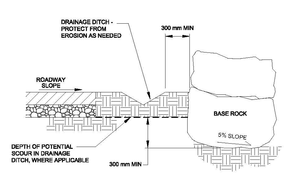
Figure 56. Graphic. Example of embedment requirements for a rockery adjacent to a roadway with a drainage ditch subject to potential scour.
View larger version of Figure 56.
Unless otherwise supplied by the Geotechnical Engineer, the allowable bearing pressure for the expected soil or rock conditions at the foundation subgrade should be determined in accordance with AASHTO Section 4.4 and clearly specified on the plans. If weak soils are encountered, the bearing capacity may be less than assumed during design and/or excessive settlement could result. If the soil is in a state in which compaction can be performed, the subgrade soils should be compacted until the desired density is achieved.
If the soil cannot be compacted (for example, the soil is too wet or soft), it will be necessary to overexcavate the foundation subgrade to expose competent soil or bedrock. In general, overexcavation and recompaction should be performed in accordance with FP-03, Sections 208.09(d) and 208.11. The maximum dry density and optimum moisture content of the fill should be determined in accordance with AASHTO T 180 and compacted to at least 90% of the maximum dry density.
Care should be taken when overexcavating for a rockery. Because passive resistance at the toe is normally neglected, the height retained by the rockery will increase due to the overexcavation, which could increase the base rock width. Therefore, the Geotechnical Engineer should be consulted whenever overexcavation is required to determine the appropriate mitigation measures. Mitigation measures could consist of constructing a wider rockery or stabilizing the base of the overexcavation with crushed rock and backfilling with crushed rock or recompacted soil.
Where a rockery is used in a marine environment, such as for a bulkhead, the rockery should be protected from erosion, particularly at the ends. In the Pacific Northwest, rockeries are either constructed such that they abut existing concrete bulkheads, or they are "returned" into the site at a 90º angle to the wall face. Where a return is constructed, the foundation excavation should extend at least three times the base rock width (3B) into the site.(1) The non-woven geotextile placed behind the rockery (as discussed later in the chapter) should extend down the entire back cut and across the entire width of the foundation excavation.
Where a rockery return is constructed on a slope, the requirements for foundation preparation depend on the slope inclination. For slopes equal to or less than 1V:2H, a sloping foundation excavation can be used in lieu of a stepped foundation. The base of the excavation should be inclined no steeper than 1V:2H, and the cross slope on the base rocks should be no greater than 1V:10H. A gravel leveling pad comprised of 100- to 150-mm (4- to 6-in) crushed rock or Foundation Fill should be constructed along the base of the foundation excavation as shown in Figure 57.
For slopes steeper than 1V:2H, it will be necessary to step the foundation to maintain the 1V:2H maximum inclination, as shown in Figure 58. The subgrade should be flat for at least a base rock width on either side of the step.
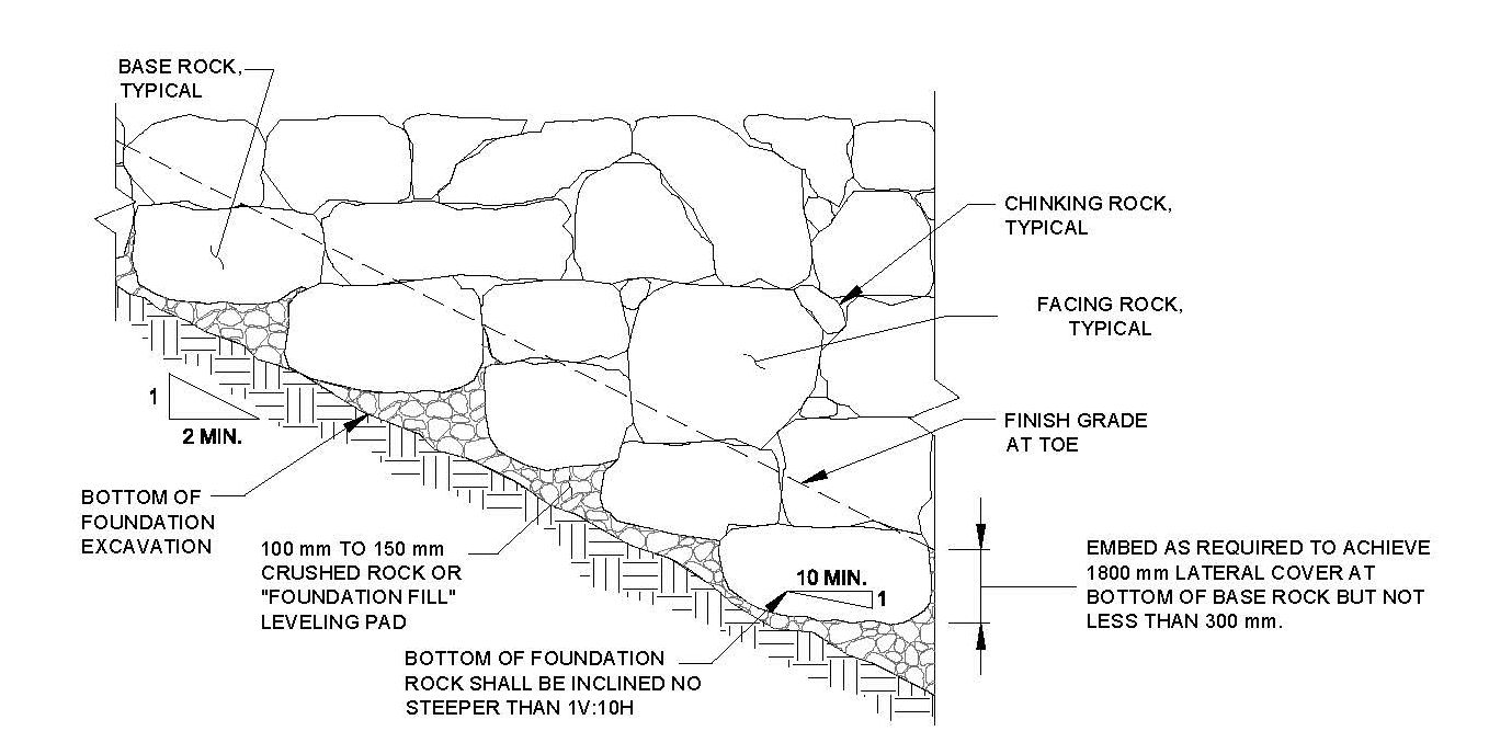
Figure 57. Graphic. Typical gravel leveling pad beneath base rocks (partial elevation).
View larger version of Figure 57.
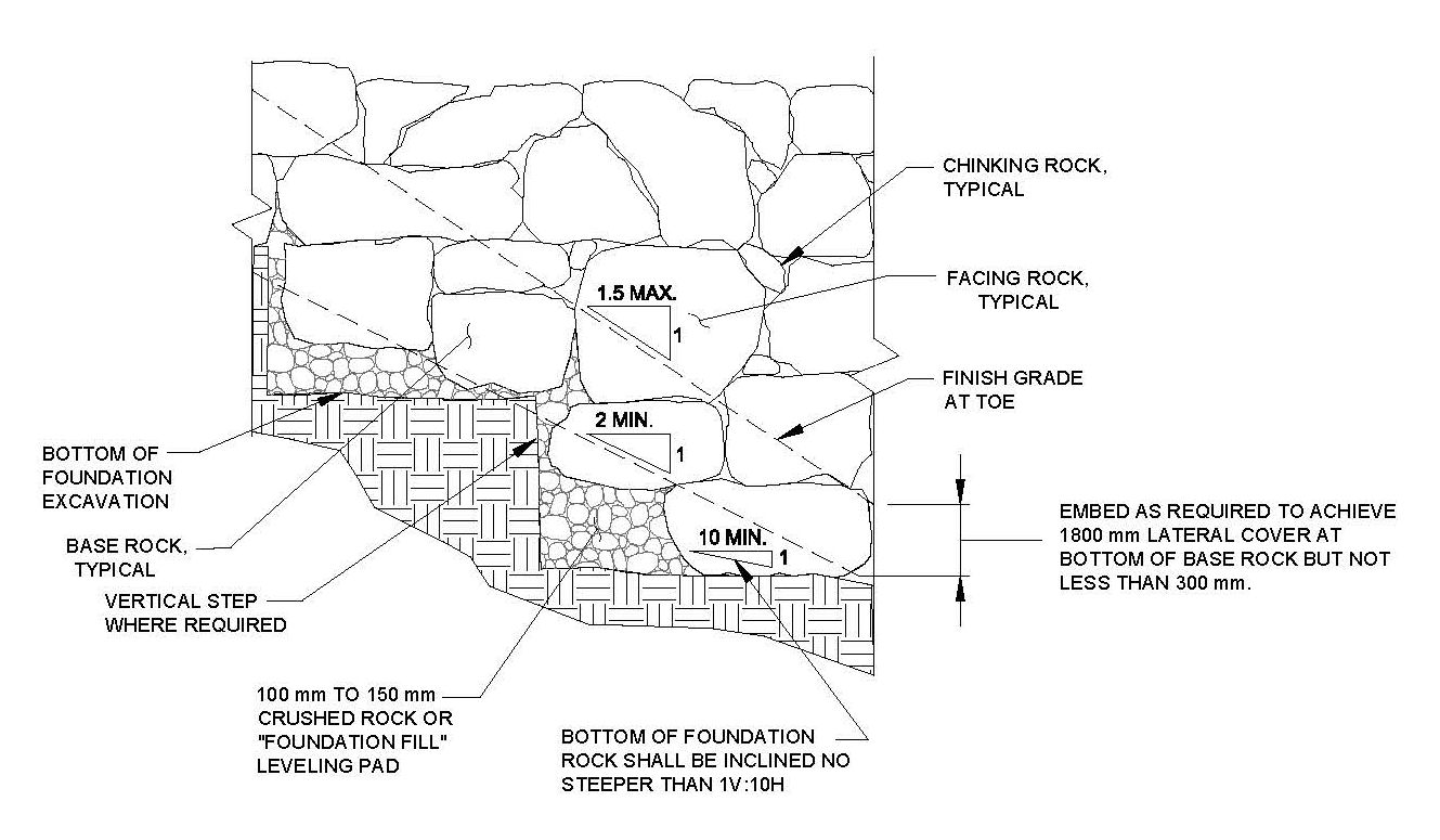
Figure 58. Graphic. Typical step in rockery foundation (partial elevation).
View larger version of Figure 58.
As with any gravity type retaining structure, back cuts are required for construction of rockeries in cut situations. Back cuts may also be required in fill situations if the fill is overbuilt and cut back before the rockery is constructed. The back cut inclination is a specified input parameter in the design procedure discussed in Chapter 4, and, therefore, the assumed inclination of the back cut should be clearly stated on the plans.
Because the allowable back cut inclination is an input value required by the Design Engineer, the Geotechnical Engineer should provide a value that is consistent with the expected soil and rock conditions as well as recognized safety regulations, such as OSHA. If the back cut must be laid back during construction due to slumping or raveling or to comply with safety regulations, changes in the lateral earth pressure on the rockery could occur, and these changes may be conservative or unconservative.
For example, if the back cut is laid back at a shallower angle than anticipated by the Geotechnical Engineer, a larger volume of crushed rock will be required to fill the space behind the rockery. As discussed in Chapter 3, this generally results in a reduction of the lateral earth pressure imposed on the rockery, which would be conservative. However, if relatively low lateral earth pressures were used during design, such as for a cut in bedrock, the lateral earth pressure imposed by the crushed rock may be higher than assumed during design, which would be an unconservative change. As a result, an earth pressure less than that for the crushed rock should never be used because there will always be a crushed rock drainage layer that will encompass a portion of the Coulomb failure wedge.
Where cuts are to be made in native soil, fill, or rock, the temporary stability of the back cut during construction should be evaluated by the Geotechnical Engineer. Although some cuts may be initially stable, they may become destabilized over time due to loss of moisture, desiccation cracking, or equipment vibrations.
Where potentially unstable soils are expected in the back cut, it made be necessary for construction to be performed in stages such that the length of time the cut is exposed is minimized. The allowable duration of exposure will vary on a case-by-case basis. In the case of stable soils, it may be possible to leave the cut exposed for weeks or months, whereas cuts in unstable soils may need to be limited to only several days of exposure. Constructing a rockery in phases, however, reduces the contractor's efficiency, and, therefore, can increase the rockery cost. Thus, phased construction should not be proposed unless warranted.
Where back cuts are made in bedrock, care should be taken to recognize potentially adverse or unstable rock conditions that may present a worker safety hazard during construction and/or could result in additional surcharge loading after the rockery has been completed. Structural discontinuities (i.e., bedding, joints, foliation, faults, etc.) present in the bedrock may be oriented such that failure could occur during or after excavation of the back cut. Two common modes of failure, planar and wedge-type failures, are shown in Figures 59 and 60. Where unstable rock conditions are recognized, a Geotechnical Engineer or Engineering Geologist should evaluate the cut and estimate the increased surcharge loads from potential failures. The Geotechnical Engineer should also review and, if necessary, revise the design recommendations to account for the increased loading conditions. Alternatively, the back cut can be laid back to a stable configuration and the resulting excavation backfilled with crushed, screened, 100- to 150-mm (4- to 6-inch) crushed rock, provided the design is checked for this condition as discussed previously.
The rocks used to construct the rockery can be obtained on-site (for example, from blasting or excavation) or imported from a quarry. The most critical physical traits of the rocks must be that they are hard, angular, and durable and will resist physical, climatic, and chemical decomposition. Rock decomposition could lead to shifting, settlement, or loss of contact between rocks. Rocks should be roughly rectangular, tabular, or cubic in shape; rounded rocks and cobbles should not be used. The rocks should consist of intact blocks without open fractures, foliation, or other planes of weakness, particularly in climatic zones prone to significant freeze-thaw conditions.
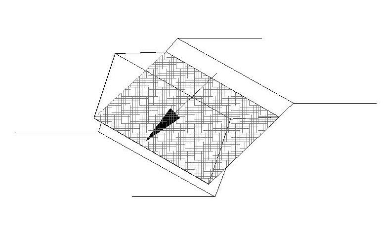
Figure 59. Graphic. Typical planar failure on an adversely oriented discontinuity that daylights in the back cut.
View larger version of Figure 59.
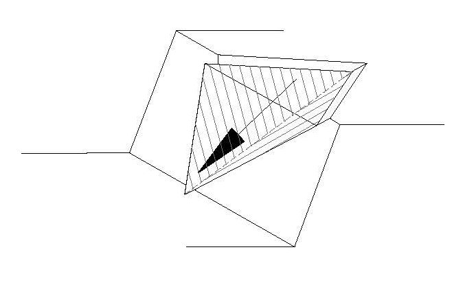
Figure 60. Graphic. Typical wedge failure on two intersecting discontinuities with a line of intersection that daylights in the back cut.
View larger version of Figure 60.
Many laboratory tests exist for determining rock soundness. Conveniently, rock quality designations and tests for riprap, which must also be hard, angular, and resistant to weathering, are generally also suitable for rockeries. Therefore, rocks used for constructing rockeries can generally be specified in accordance with FP-03, Section 705.02, Riprap Rock, which includes the following minimum properties:
In addition to the requirements of Section 705.02, rocks used for rockeries should also meet the following minimum requirements:
The additional requirements are based on other commonly referenced riprap standards, including the California Department of Transportation (CalTrans) Standard Specification 72 - Slope Protection, Section 2.02, (12) and FHWA Hydraulic Engineering Circular 11 (HEC 11), Appendix A - Suggested Specifications, Section 7.1.2a. (22)
As discussed previously, rocks used to construct a rockery should be generally rectangular, tabular, or cubic in shape. Rocks that are triangular in shape can be difficult to stack in a stable configuration. However, it may be difficult to obtain a significant number of ideal, rectangular rocks. If irregular rocks with steeply pitched edges must be used, they should be matched with other irregular rocks such that generally level bearing surfaces with a gradual backward tilt into the back cut are formed. Examples of rectangular and matched irregular rocks are shown in Figure 61.
In general, rounded rocks, such as cobbles or river rocks, should not be used. The rounded nature of the rocks reduces the potential for interlocking and generally results in a less stable structure. Where protecting rockeries are constructed against relatively flat slopes, it may be feasible to use rounded rocks if that is the only locally available material. However, the use of rounded rocks should be avoided and the acceptability of using rounded rocks should determined by either the Design Engineer or Geotechnical Engineer on a case-by-case basis.
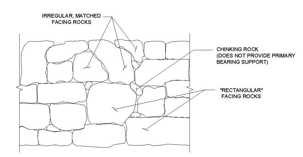
Figure 61. Graphic. "Rectangular" and "matched irregular" facing rocks (partial elevation).
View larger version of Figure 61.
Proper placement of the rocks comprising the rockery requires skill and experience because of the irregular and non-uniform nature of the materials involved. In many ways, a rockery is like a jigsaw puzzle. Some rocks only fit in some places and not others, and finding the proper match between rocks to form a stable structure can be a trial-and-error process even if the operator is highly experienced.
Because the rocks must be "finessed" into proper interlocking positions, the use of proper equipment for rock placement can be the difference between a successful and unsuccessful project. While the rocks for some early rockeries were moved by hand - hence the term "man rocks" - the use of modern hydraulic equipment greatly eases and speeds construction. Perhaps the most useful piece of modern equipment used for rockery construction is the hydraulic excavator with a rotating clamshell attachment, as shown in Figure 62. The clamshell allows the rock to be grasped uniformly on two sides, and the powered rotation capability allows the operator to quickly make adjustments to the rock orientation and alignment. In addition, a clamshell with rotation capability also allows one rock to be placed and replaced at multiple locations to determine the best fit without the need to move the excavator or regrasp the rock.
An excavator with a rotating clamshell should be specified in the plans, as it improves rockery construction and reduces time of installation.
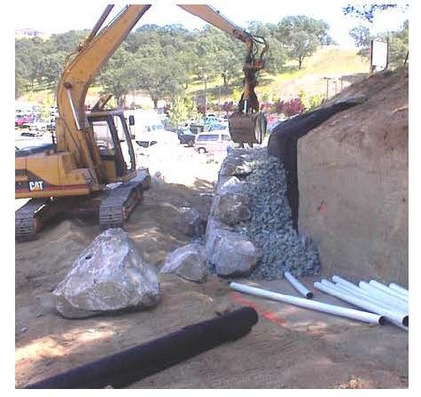
Figure 62. Photograph. Hydraulic excavator with a clamshell constructing a rockery.
If a clamshell is not available, an excavator with a "thumb" can also be used, as shown in Figure 63. However, the capability to carefully align the rocks is much more limited, particularly without numerous small movements of the excavator. In addition, because the rocks should be placed with the long dimension into the slope, the use of a "thumb" requires the rocks to be placed from the side, rather than in front, of the rockery. In general, the use of "thumb" type equipment should not be allowed except on relatively small jobs. It should be noted that due to the nature of the thumb, the rock in Figure 63 is being placed with its largest dimension parallel to the face of the wall, rather than perpendicular, which is not preferred.
Base rocks should be placed on a properly prepared foundation excavation, as discussed previously. The minimum base rock width, B, should be specified on the plans and should be based on overall rockery height, retained soil properties, and any surcharge loads. All rocks, including the base rocks, should be placed with the longest rock dimension perpendicular to the face of the rockery. The second largest dimension should be parallel to the layout line of the rockery, and the smallest rock dimension should be its vertical dimension. The base rocks should be placed such that the tops of the rock are sloped back at least 5% towards the back of the rockery.
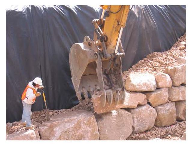
Figure 63. Photograph. Placement of facing rocks using an excavator with a "thumb."
View larger version of Figure 63.
The allowable tolerance for base rock widths should be 150 mm (6 in). However, two or more consecutive base rocks should be not be placed with a width less than specified on the plans, and the overall use of base rocks with a width less than β should be minimized. Once required base rock widths exceed 1700 m (5.5 ft), locating and transporting rocks with the required minimum width becomes difficult. In these circumstances, it is reasonable to use two equally sized rocks with a total width of at least B, provided the rocks are bearing against each other in at least two locations, as shown in Figure 64. Due to limitations in current analysis techniques, facing rocks above the base rock should only consist of single rocks that provide the required rockery width.
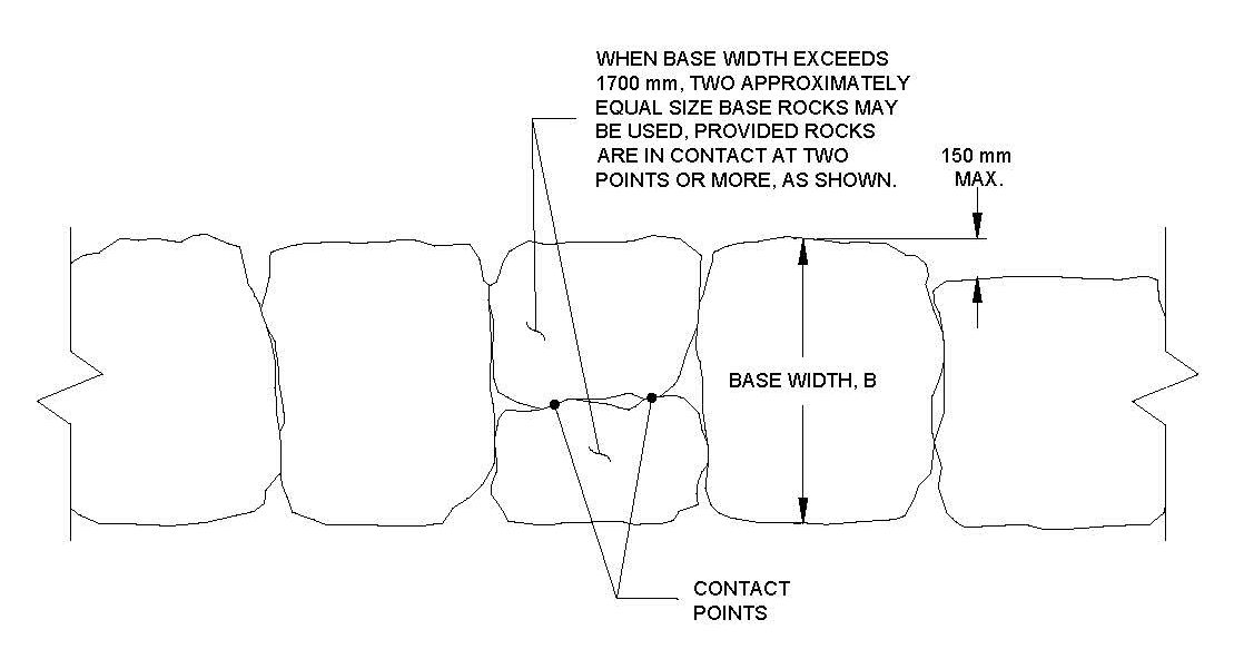
Figure 64. Graphic. Base rock tolerances and use of two base rocks to achieve "B" (partial plan view).
View larger version of Figure 64.
Successive lifts of facing rocks should be placed above the base rocks in accordance with the design schedule. In general, the width of successive rows of facing rocks will be determined based on the design rockery face batter, which will generally vary between 4V:1H and 6V:1H. Each rock should be placed according to the following guidelines:
When looking at the face of the rockery, the rocks should be stacked in an approximate "running bond" pattern; that is, there should be no vertical columns of rock or continuous vertical joints running through the rockery. Continuous horizontal joints should also be avoided. The rocks should be selected and stacked such that most of the rocks in a given row are approximately the same size and gaps between rocks are minimized. Rocks with shapes that create voids with a linear dimension greater than 300 mm (12 in) shall be placed elsewhere to obtain better fit. It may be necessary to place rocks at several locations to determine the best fit for a given rock. If gaps larger than 150 mm (6 in) cannot be avoided, they should be chinked (filled) with smaller rocks. However, chinking rocks should not provide primary bearing support for overlying rocks. Chinking rocks are discussed in more detail later in this chapter.
Examples of acceptable and unacceptable alignment relative to the rockery cross section are shown in Figure 65. A typical elevation showing examples of improper rock placement is shown in Figure 66.
An example of a relatively well constructed rockery is shown in Figure 67. Although a few vertical seams can be located, the rocks are generally bearing at the proper locations and stacking in an approximate running bond pattern.
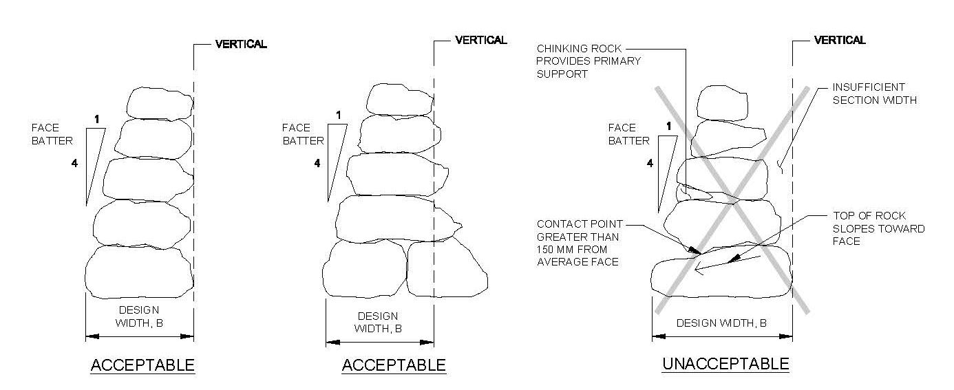
Figure 65. Graphic. Examples of acceptable and unacceptable rockery alignment.
View larger version of Figure 65.
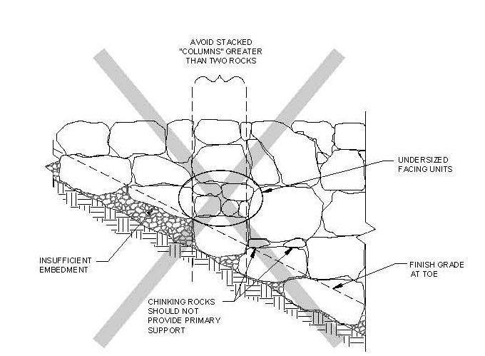
Figure 66. Graphic. Examples of improper rock placement (partial elevation).
View larger version of Figure 66.
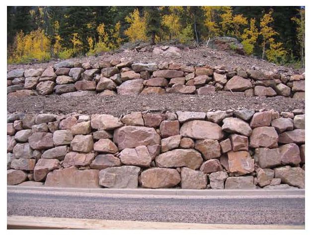
Figure 67. Photograph. Example of a relatively well constructed rockery.
View larger version of Figure 67.
Photographs of unacceptable rock bearing and chinking are presented in Figures 68 and 69. Note the wide gaps and main bearing point at the rear of the rockery. In addition, the rocks are not bearing directly on adjacent rocks.
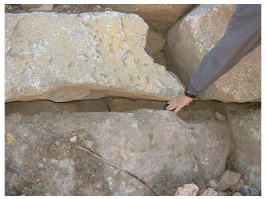
Figure 68. Photograph. Example of an unacceptable rock bearing.
View larger version of Figure 68.
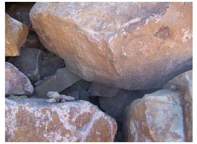
Figure 69. Photograph. Example of improper rock bearing and lack of chinking.
View larger version of Figure 69.
The crushed rock zone placed behind the rockery facing is an important component of the overall rockery system. It addition to providing drainage, the crushed rock improves overall rockery stability by providing a high strength material behind the facing rocks. This material helps to reduce the overall soil pressure on the rockery system.
The crushed rock should consist of 100- to 150-mm (4 to 6-in), crushed, and screened, angular rock. This material is often called "quarry spalls," and should meet the gradation requirements presented in Table 9.
| Sieve Size | Percent by Mass Passing Designated Sieve (AASHTO T 27 & T 11) |
|---|---|
| 150 mm (6 in.) | 100 |
| 100 mm (4 in.) | 0.0 - 25 |
| 19.0 mm (3/4 in.) | 0.0 - 15 |
| 4.75 mm (No. 4) | 0.0 - 5.0 |
| 75 μm (No. 200) | 0.0 - 2.0 |
The crushed rock should fill be void between the back cut and the rear of the facing rocks; however, it should be 300 mm (12 in) wide as a minimum. The crushed rock should be capped by at least 300 mm (12 in) of impermeable soil at the ground surface to prevent infiltration of surface water behind the rockery.
During placement of the crushed rock behind the partially completed rockery, care should be taken that the crushed rock does not spill over the top of the adjacent facing rocks. If the crushed rock is placed between the top of one facing rock and the base of the subsequent facing rock, it could form a place of weakness or prevent the facing rocks from coming into proper contact. Like chinking rocks, the crushed rock should not provide primary bearing between rocks. It is acceptable, however, for the crushed rock to fill a portion of the lateral void between adjacent facing rocks, provided the rocks are in directly in contact in at least two points.
As the base and facing rocks are placed, is it generally most convenient to construct the rockery backdrain and crushed rock zone concurrently. The backdrain pipe should generally consist of a 100-mm-diameter (4-in-diameter) perforated drain pipe surrounded on all sides by at least 100 mm (4 in) of screened, 100- to 150-mm (4- to 6-in), angular crushed rock unless unusual conditions exist as determined by the Geotechnical Engineer. The drain pipe should consist of either corrugated high-density polyethylene (HDPE) pipe or smooth polyvinyl chloride (PVC) pipe conforming to FP-03, Section 706.08(d) or 706.08(e). The pipe should be placed with the perforations down. A diagram of the backdrain components is presented in Figure 70 and photographs of installed crushed rock backdrains are presented in Figures 71 and 72.
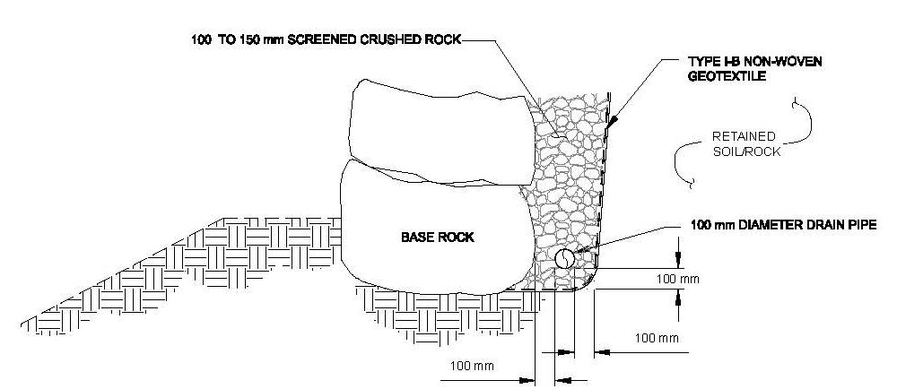
Figure 70. Graphic. Backdrain components (partial section).
View larger version of Figure 70.
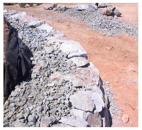
Figure 71. Photograph. Example of crushed rock placed behind rockery.
View larger version of Figure 71.
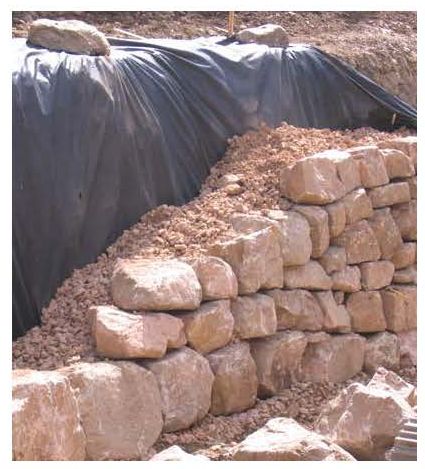
Figure 72. Photograph. Placement of drain blanket and non-woven geotextile behind rockery.
Where tiered rockeries are constructed, drainage of the upper tier is an important detailing consideration. Typically, it is difficult to outlet the backdrain directly from the upper tier because it is typically located mid-slope. In these circumstances, the perforated drain pipe can be tied into solid discharge pipes and directed downslope. The solid pipes should be sloped to the back of the lower tier, taken down the back of the lower rockery, and outlet at a similar location as the lower tier drainage. The drainage systems for the rockeries should not be interconnected, so separate discharge pipes will be required for both the upper and lower tier rockeries.
The pipes should generally be outlet at all low points of the base rock subgrade, at a spacing not to exceed 30 m (100 ft). The outlet pipes should be sloped to drain to a controlled drainage structure. The drainage structure can consist of a storm drain catch basin, storm drain pipe, or riprap-lined roadside ditch. Because of the increased use of Best Management Practice (BMP) mitigation measures to meet storm water discharge requirements, many storm drain systems are being designed to store storm water during heavy rainfall events. The discharge pipes for the backdrain system should not be connected directly to such systems unless the hydraulic grade line for the storage system is below the elevation of the drain pipe behind the rockery. The purpose of this recommendation is to prevent storm water from flowing backwards through the system and out the face of the rockery.
For rockeries constructed on the downhill side of a roadway, it may not be feasible to connect the discharge pipe to the storm drain system and a downslope outfall may be needed. If an outfall is used, the outlet should be protected through the use of an energy dissipater and riprap splash pad. In addition, the Geotechnical Engineer should confirm that surficial slope instability and/or erosion is not a concern due to the increased moisture content caused by the outfall.
The soil retained by the rockery must be protected against "piping," particularly where seepage is observed in the back cut. "Piping" is a process through which fine-grained soil particles are transported from the soil medium into a void by subsurface water flow. Piping can result in loss of ground, ground surface settlement, and ground instability. Because of the large void ratio inherent to screened 100- to 150-mm (4- to 6-in) crushed rock, the potential for subsurface water to pipe fines into the crushed rock is relatively high. Therefore, the crushed rock should be separated from surrounding soil surfaces by a non-woven geotextile. To prevent gaps that could circumvent the filter protection and lead to piping, all seams in the geotextile should be overlapped by at least 300 mm (12 in).
The non-woven geotextile should conform to the requirements of FP-03, Section 714, Type I-B geotextile. All geotextiles used for filtration should consist of non-woven fabrics comprising long-chain synthetic polymers, at least 95% of which are polyolefin or polyester. Woven, slit- film separation fabrics should not be allowed. All geotextile rolls should be delivered to the job site wrapped in a protective plastic sheeting to protect the geotextile from damage during shipment, contamination by soil and mud during storage on-site, and from ultraviolet (UV) degradation due to sunlight.
For most rockery applications, a Type I-B geotextile should provide an acceptable level of performance and survivability. A Type I-B geotextile should have the minimum properties presented in Table 10. All values, with the exception of Apparent Opening Size (AOS), are presented as minimum average roll values (MARV). Values of AOS are maximum average roll values.
In addition to the properties presented in Table 10, a filtration calculation should be performed to check that the geotextile is compatible with the retained soil conditions. For soils with greater than 50% of the material passing the 0.075 mm (#200) sieve, a Type I-C geotextile is likely more appropriate.
| Property | Elongation ≥ 50% |
|---|---|
| Grab Tensile Strength | 700 N |
| Sewn Seam Strength | 630 N |
| Tear Strength | 250 N |
| Puncture Strength | 250 N |
| Burst Strength | 1,300 N |
| AOS | 0.25 mm max. |
| Permittivity | 0.2 sec-1 |
If harsh installation conditions are expected that could damage the non-woven geotextile, the Geotechnical Engineer should consider a Type IV-B non-woven geotextile for additional protection and geotextile strength. For soils with more than 50% of the material passing the 0.075mm (#200) sieve, a Type IV-C geotextile is likely more appropriate.
In addition to subsurface water, surface water must also be controlled. To prevent a hydraulic connection between the rockery backdrain and surface water flows, the top of the crushed rock should be capped with at least 300 mm (12 in) of "impermeable" soil over non-woven geotextile. This soil cap can generally consist of on-site soils and should be "impermeable" to the extent that rapid infiltration of surface water cannot occur.
As with any structure that retains soil or rock, surface water should also be directed away from the rockery where possible. Where the rockery is constructed at the toe of a slope or on a slope, a v-ditch consisting of concrete or impermeable soil should be constructed immediately behind the rockery to direct surface water to a suitable drainage outlet, as shown in Figure 73. In rare circumstances, the surface water drain system can be designed to allow "minor" surface water to enter the backdrain provided the drainage system is sized for the increased flow. Because it is difficult to limit surface water to "minor" amounts, this practice is generally not recommended.
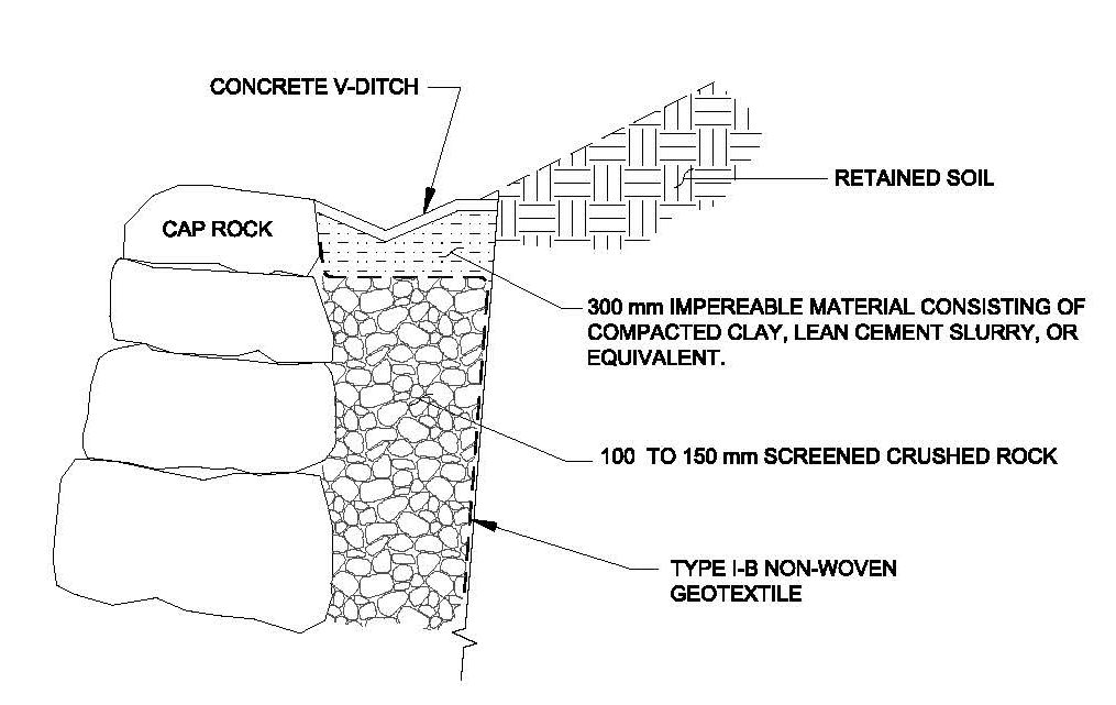
Figure 73. Graphic. V-Ditch and impermeable cap at top of rockery (partial section).
View larger version of Figure 73.
The final rock placed at the top of the rockery is the cap rock. Because the cap rock provides a finished look to the top of the rockery, it is generally smaller and flatter than the facing rocks. To reduce the risk of disturbance to the cap rocks, such as by vandals or rock climbers, cap rocks should weigh at least 90 kg (200 lb). In addition, cap rocks should not be movable by hand. Cap rocks that do not meet these minimum requirements should be grouted or glued in place to prevent accidental dislodging.
Particular care should be taken when placing and sizing cap rocks for rockeries with toe slopes. If improvements are located at the base of the slope, dislodged rocks could roll down the slope and pose a significant hazard. Where this condition occurs, consideration should be given to securely grouting all cap rocks regardless of size.
Because of the irregular nature of the rocks, it is difficult to ensure that every rock conforms to the shape of all adjacent rocks. As a result, gaps will occur between rocks. Where these gaps exceed 150 mm (6 in), they should be filled with chinking rocks consisting of spalls from the parent (facing) rock. The purpose of the chinking rocks is to improve aesthetics and prevent the screened backdrain material from falling out through the face of the rockery. Chinking rocks should not be movable by hand, and can be grouted in place if necessary. In addition, chinking rocks are not to provide primary support for overlying rocks.
In fill conditions, the engineered fill is typically placed before rockery construction and trimmed to the desired back cut. However, in the rare cases, backfill may need to be placed behind the rockery concurrent with or after rockery construction.
If soil backfill is placed and compacted behind a rockery, full-size, ride-on compaction equipment should not be used within a distance of 0.75H or 1500 mm (5 ft), whichever is greater, from the back of the rockery because of the potential to surcharge the back of the rockery. Compaction adjacent to the rockery should be performed using hand-operated compaction equipment such as a J-tamper ("jumping jack") or whacker plate ("turtle"). In addition, it is recommended that the backdrain width be increased to 600 mm (24 in) to provide additional space between the back of the rockery and the compaction zone.
The backfill material, whether placed before or after construction, should conform to the requirements for Select Topping per Section 704.08 of FP-03. Specifically, the material should meet the following requirements:
In addition, the backfill material should have a friction angle (φ) greater than or equal to the value specified by the Geotechnical Engineer. The minimum friction angle should be shown on the plans.
Backfill should be placed and compacted in accordance with FP-03, Sections 208, Structure Excavation and Backfill for Selected Major Structures. Specifically, backfill should be placed and compacted in accordance with Sections 208.10 and 208.11. This requires placement of backfill in 150 mm (6 in) loose lifts. The backfill should be compacted to at least 95% of the maximum dry density, as determined by AASHTO T 99, or to at least 90% of the maximum dry density per AASHTO T 180. The Geotechnical Engineer should identify any additional site- specific compaction requirements relative to the soil types present at the project, such as moisture conditioning requirements.
Where MSE fills are constructed, they too should be overbuilt and cut back wherever possible. Geosynthetic selection, placement procedures, and backfill quality and compaction requirements for MSE fills should conform to the recommendations in the FHWA MSE and RSS manual.(20)
A test section generally consists of constructing a limited length of rockery, typically 6 to 9 m (20 to 30 ft), so that the materials, workmanship, and appearance can be checked. Construction of test sections is typically not performed for most rockery projects. However, under certain circumstances, it may be advantageous for the contractor to install a test section prior to the start of production rockery construction. These circumstances could include:
Under these conditions, the Design Engineer should specify in the contract documents that a test section shall be constructed, and that award of the remaining portion of the contract is contingent on acceptance of the completed test section by the Design Engineer.
Stay up to date
Sign up for announcements on grant opportunities, training, and webinars.