Previous Chapter « Table of Contents » Next Chapter
Based on the thousands of commercial rockeries in existence that are performing well, rockeries can be a dependable and effective retaining solution provided they are properly designed, detailed, and constructed. In this respect, rockeries are no different from conventional reinforced concrete retaining walls or mechanically stabilized earth or embankment (MSE) walls. While there is no question that a well-designed rockery that is constructed poorly will perform poorly, the evidence indicates that well-constructed, modern rockeries still perform well even though the design procedures used may vary considerably.
A primary objective of this study is to develop rational design procedures that can be used by Federal Lands Highway (FLH) geotechnical engineers for the design of future rockeries and evaluation of existing rockeries. Rockeries are composed of large blocks of stacked rock, heavy enough and dimensionally adequate to form a structure that resists overturning and sliding forces. In this respect, rockeries can be treated as gravity walls, and can be analyzed rationally using modified forms of conventional gravity retaining wall design methodologies.
Design of any retaining structure involves the determination of two categories of forces - driving forces and resisting forces. For rockeries, driving forces may include lateral earth pressures behind the rockery, surcharge pressures (both vertical and horizontal), hydrostatic fluid pressures, and seismic pressures. Resisting forces can include the total weight of the rockery and individual rocks, inter-rock friction, base rock - foundation friction, and, in some cases, passive pressure at the toe of the rockery. Where Coulomb earth pressures are used, the vertical component of the active earth pressure can also aid in stabilizing the rockery.
A typical rockery section is shown in Figure 30, along with the design parameters and dimensions that must be determined prior to rockery design. Driving forces include those from the active soil pressure (FA) and surcharge loads (FS). Resisting forces include base friction (Fμ) and passive resistance (FP), if used.
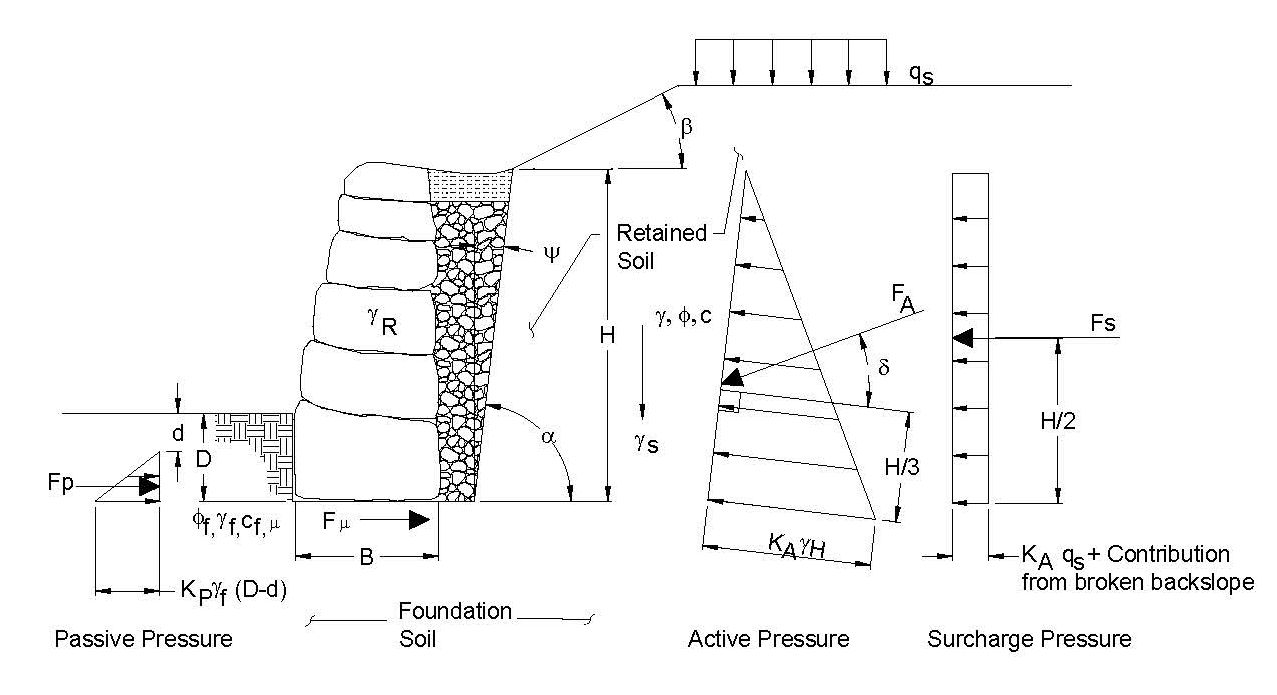
Figure 30. Graphic. Schematic rockery section showing critical dimensions and parameters to be determined for design.
View larger version of Figure 30.
For design, the project Geotechnical Engineer should provide the following geotechnical parameters:
In most cases, rockeries are assumed free to rotate about the base, and the earth pressure is typically computed by multiplying the lateral earth pressure coefficient for active soil conditions (KA) by the unit weight of the soil (γs). Because the resulting value has the units of density (Force/Length3), it is often expressed in terms of an equivalent fluid pressure (EFP) of retained soil. A more detailed discussion of lateral earth pressures may be found in most foundation engineering textbooks, such as those by Das (14) or Bowles.(15)
For most rockeries, there are two potential sources of lateral earth pressure acting on the back of the rockery - that exerted by the retained soil, and that exerted by the crushed rock backdrain. Generally, the pressure exerted by the crushed rock backdrain is less than that exerted by the retained soil, for three reasons:
Consequently, for most rockery design cases, the theoretical failure plane crosses through two soil types (crushed rock and retained soil) and a compound failure wedge is developed. While it is feasible to develop closed-form equations for this condition, acceptable results can be obtained by making the simplifying assumption that the crushed rock is part of the rockery system and the lateral earth pressure is developed solely by the retained soil. Therefore, the lateral earth pressure acts on the back of the crushed rock layer at the crushed rock/slope interface rather than the back of the rockery facing elements. Because the friction angle of the crushed rock is almost always greater than that of the retained soil, this simplifying assumption is usually conservative.
However, as demonstrated previously by example Case #4 (Figure 24), this procedure may not be conservative under all conditions. Where the soil slope is laid back at a relatively shallow inclination (greater than 2V:1H), the value of KA computed for the soil slope would likely be lower than for a wide zone of crushed rock backfill. Under these conditions, the lateral earth pressures for both the crushed rock backfill and the soil slope should be evaluated, and the larger value should be used in the design.
The Coulomb method, which accounts for frictional interaction between the retained soil and the retaining structure, is the recommended method for determination of KA. In this case, the "back of the retaining structure" is actually the back of the crushed rock backdrain. Because of the roughness of the crushed rock layer, the interface friction angle, δ, is assumed equal to the friction angle of the retained soil, φ. Where a filter or separation fabric is used between the retained soil and the crushed rock backfill, a value of 2/3φ may be more appropriate. Figure 31 presents an equation for the computation of KA using the Coulomb method that accounts for soil strength, back cut inclination (ψ), and ground surface inclination (β).
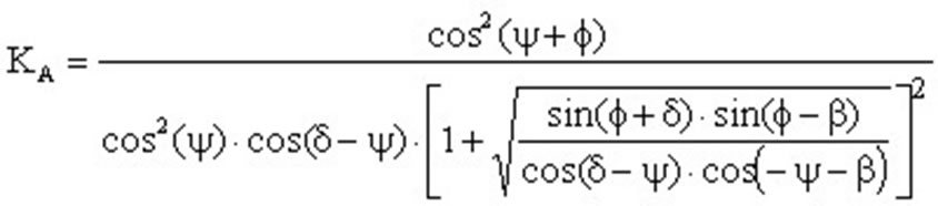
Figure 31. Equation. Determination of lateral earth pressure coefficient, KA, using the Coulomb method.
The back cut angle (ψ) used in Figure 31 is measured back from the slope face from the vertical. However, the slope inclination is often described by as angle measured up from horizontal, designated α. The value of a is equal to 90º - ψ.
For values of ψ greater than about 20º (α less than about 70º), the value of KA begins to decrease rapidly and a "protecting rockery" condition may exist. Under these conditions, the lateral pressure applied by the crushed rock backfill should be checked to determine if it is more critical than the retained soil. In addition, a global slope stability analysis may be required to determine if the overall stability of the slope is acceptable.
The preceding discussion assumes that non-expansive materials are exposed in the back cut. If highly plastic native clay or expansive bedrock is present in the back cut, surcharge pressures could be imposed on the back of the rockery due to swelling caused by seasonal moisture change. Special design considerations are required under these conditions and should be evaluated by the Geotechnical Engineer.
Once the earth pressure coefficient has been determined, the horizontal forces acting on the back of the rockery due to both the retained soil (FA,H) and any surcharge loads (FS) can be determined. For a uniform vertical surcharge, qS, applied to the ground surface behind the rockery, the horizontal active earth pressure imposed can usually be estimated as the quantity KA·qS .
The standard American Association of State Highway Transportation Officials (AASHTO) traffic surcharge(16) is assumed to be equivalent to 0.6 m (2 ft) of additional soil stockpiled above the rockery. For this condition, the value of qS is computed as γS(0.6 m). Therefore, assuming a soil unit weight of 20 kN/m3(125 pcf) the total traffic surcharge force per unit width (FS) of rockery (FS) can be computed as 12KAH kN/m (250KAH lb/ft).
According to Coulomb theory, the lateral earth pressure force acts at an angle δ from the perpendicular relative to the back of the retaining surface, where δ is defined as the interface friction angle. However, the back of the crushed rock backdrain, which is inclined at an angle ψ back from vertical, is conservatively used as the back of the retaining surface. Therefore, the inclination of the lateral earth pressure force must be adjusted to determine the correct magnitude of the horizontal component. The equation for computing the horizontal force acting on the back of the rockery appears in Figure 32.

Figure 32. Equation. Horizontal force on back of rockery, equal to the sum of the lateral earth pressure and any surcharge loads.
Rockeries generally resist sliding primarily through friction along the bottom of the base rock, which is a function of the normal force acting on the base of the rockery and the coefficient of sliding between the base rock and foundation soil. The normal force consists of the vertical component of the Coulomb active earth pressure (FA,V, acting downward) and the weight of the rockery.
The weight of the rockery can be estimated by assuming certain minimum dimensions for the rockery, breaking the rockery into a few easy to define geometric shapes, assuming a unit weight for the rockery mass, and computing the total weight as the sum of each component. The unit weight of the individual, sound, intact rocks is about 25.9 kN/m3 (165 pcf), which corresponds to a specific gravity of about 2.65. However, once the voids in the rockery are considered, a reasonable unit weight for a well-constructed rockery is about 23.6 kN/m3 (150 pcf). The Geotechnical Engineer should evaluate the supply of locally available rocks and determine if these parameters are valid at the start of the project.
Figure 33 shows an example of a rockery that has been divided into three sections for the computation of the rockery weight. Although the lateral earth pressures are assumed to act on the back of the crushed rock backdrain behind the rockery, the weight of the crushed rock is typically not included as a resisting force. Because the crushed rock is not physically connected to the back of the rockery and the facing rocks and crushed rock interact only through frictional contact, it is not clear that the weight of the crushed rock would provided a significant resistance to movement, particularly overturning. Therefore, the weight of the crushed rock is conservatively neglected. After the design is complete, the final rockery dimensions should be checked to verify the assumed geometry and weight are correct.
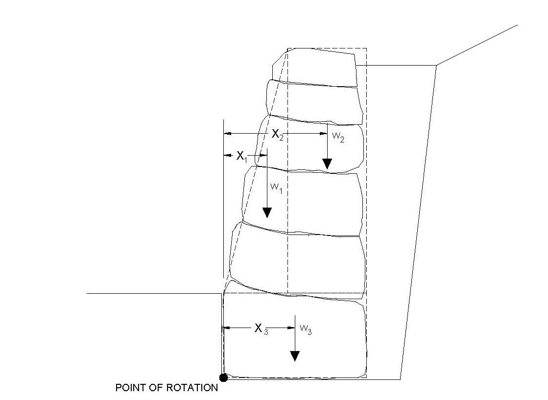
Figure 33. Graphic. Estimation of rockery weight and centroidal distances.
View larger version of Figure 33.
The friction along the bottom of the base rock is computed by multiplying the friction factor for sliding between the rock and the foundation soil (μ) by the sum of the vertical forces acting on the base of the rockery. The value of μ, which is related to the roughness of the base rock, the internal friction angle of the foundation soil (φ), and the degree of "nesting" or interaction between the two, should be determined by the project Geotechnical Engineer for each anticipated subgrade material. Typical values of μ for some common materials are listed in Table 7.
The values of μ presented in Table 7 are ultimate values; that is, they are unfactored. In the western United States, it is common practice to reduce the magnitude of the friction coefficient when passive and friction are considered concurrently because differing amounts of rockery movement are required to develop the peak values of each. The implementation of this reduction varies regionally. For the design procedures presented in this report, a factor of safety of 1.5 is recommended where passive resistance and friction are used concurrently. Where passive pressure is neglected completely, reduction of the frictional component is not required.
| Base Rock Texture | Foundation Material | Estimated Ultimate Friction Factor, m |
|---|---|---|
| Rough | Dense, medium-grained sand φ=36º | 0.7 |
| Smooth, angular rocks with flat faces | Stiff silt or clay
φ=30º |
0.4 |
| Rough | Moderately weathered bedrock
φ=36º |
0.6 |
| Rough | 300 mm thick layer of crushed rock
φ=40º |
0.8 |
| Smooth, angular rocks with flat faces | 300 mm thick layer of "foundation fill" with 100% passing 50 mm sieve, 6% maximum passing 75 mm sieve
φ=35º |
0.7 |
Figure 34 presents the equation for the computation of the friction force on the base of the rockery.
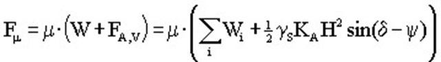
Figure 34. Equation. Computation of frictional resistance along the base of the rockery.
The equation presented in Figure 34 is only valid for values of ψ ≤ δ. Where ψ exceeds δ, there is a reversal of the computed direction of the vertical component of the lateral earth pressure force; that is, it acts upward instead of downward. However, under these conditions, the back- cut inclination is likely shallow enough that retention of the crushed rock backfill will control the design.
Passive resistance at the toe of the rockery can, in some circumstances, also resist horizontal sliding. However, passive resistance should be used with care, as construction practices can have a significant impact on the magnitude of the passive resistance. Unlike concrete footings, which are typically cast against a vertical soil cut, the foundation for a rockery is generally constructed by excavating to the foundation depth and placing the base rock in the foundation excavation. The base rock may or may not be in solid contact with the face of the excavation, and significant lateral movement may be required to develop any appreciable lateral resistance. As a result, passive resistance should only be included if the project specifications include recompaction of the soil against the toe of the rockery. Because it is often difficult to enforce and/or verify uniform compaction at the toe of the rockery without full-time construction observation and testing, it is recommended passive resistance be neglected completely. In addition, passive resistance should not be used if there is a potential for soil to be removed from the toe after construction, such as in the case of scour.
If it is desired to include passive resistance, a Rankine passive pressure coefficient yields a more conservative resisting value than a Coulomb coefficient and is recommended for use. The use of a Rankine coefficient for this application also appears to be in line with current geotechnical standard of practice. Because Rankine pressures neglect the influence of friction between the soil and the rockery, the pressure acts horizontally.
Figure 35 presents the recommended equations for computation of the passive pressure at the toe of the rockery; φF is the friction angle of the soil in front of the rockery, which may be different than that for the retained soil. The value D is the depth of embedment of the base rock, that is, the distance from the ground surface at the toe to the bottom of the rockery. The value d is the depth of soil to neglect when performing the passive resistance computation. Within the geotechnical community, it is common practice to neglect the upper 300 mm (12 in) of soil when calculating passive resistance, unless the soil at the toe of the rockery is protected by a slab or pavement. For rockeries founded 300 to 450 mm (12 to 18 in) below grade, D ≈ d, which is yet another reason why passive resistance should often be neglected completely.
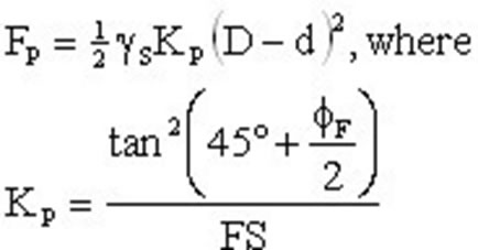
Figure 35. Equation. Evaluation of passive resistance at the rockery toe.
The factor of safety used in the definition of KP is included to limit the amount of rotation and deflection required to develop the maximum value of passive resistance. A factor of safety of 1.5 is typically assumed for this application. However, considering the difficulty in uniformly compacting soil against the uneven face of a rockery, a larger factor of safety may be justified to limit the amount of resistance that is relied upon. The actual factor of safety used should be selected by the Geotechnical Engineer based on the tolerable amount of horizontal movement by the rockery. Additional discussions regarding wall rotation and passive resistance are presented in Das, (14) Bowles,(15) and NAVFAC.(17)
Once the forces described above have been determined, the factor of safety against sliding can then be defined as the ratio of the resisting forces (Fμ, FP) to the driving forces (FH), as shown in Figure 36. A minimum factor of safety of 1.5 should be used to check against sliding.
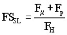
Figure 36. Equation. Expression for factor of safety against sliding (FSSL).
In addition to the tendency to cause translational movement, the forces acting horizontally behind the rockery will also tend to cause it to tip forward about its toe. These forces include the horizontal component of the lateral earth pressure (FA,H) and the additional horizontal pressure due to a vertical surface surcharge (FS). The overturning moments caused by these forces are counterbalanced by resisting moments due to the weight of the rockery (W), the vertical component of the lateral earth pressure (FA,V), and the passive resistance at the toe of the rockery (FP). The overturning and resisting moments are computed by summing moments about the toe of the rockery as illustrated in Figures 37 and 38. The total resisting moment due to the weight of the rockery is computed for each component of the rockery weight (Wi) multiplied by the horizontal distance from the centroid of each rockery segment to the toe of the rockery (xi). A graphical example showing the locations of the centroidal distances was previously presented as Figure 33. The factor of safety is computed as shown in Figure 39.
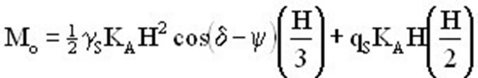
Figure 37. Equation. Determination of overturning moments about the toe of the rockery.

Figure 38. Equation. Determination of resisting moments about the toe of the rockery
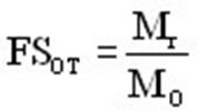
Figure 39. Equation. Determination of factor of safety against overturning.
A minimum factor of safety of 2.0 should be used for FSOT. Although the resisting force applied by passive resistance at the toe is shown in Figure 38, it is recommended that passive pressure be neglected for the reasons discussed previously.
The factor of safety against internal (inter-rock) overturning can normally be addressed through proper specification and construction practices, because the coefficient of sliding and section properties within the rockery itself typically produce internal stability results that exceed those for external rockery stability. As a practical note, the internal stability requirements are generally met if the first point of contact between upper and lower rocks is no more than 150 mm (6 in) from the face of the rockery.
However, if large surcharge loads are applied above the rockery, inter-rock overturning or sliding should be checked, particularly near the top of the rockery. Internal overturning is evaluated in the same manner as external overturning, except moments are summed about the base of the section of rockery under consideration, rather than about the base of the entire rockery cross-section. Internal overturning stability at any point in the rockery can be computed using the equations presented in Figures 40 and 41. For these equations, it is assumed:
The geometry is defined graphically in Figure 42. As with external overturning, a minimum factor of safety (FSOT_int) of 2.0 should be used to check the internal overturning analysis.
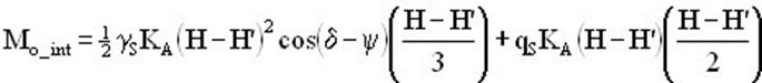
Figure 40. Equation. Calculation of internal overturning moment at a distance H' from the base of the rockery.
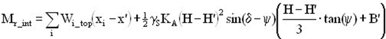
Figure 41. Equation. Calculation of internal resisting moment at a distance H' from the base of the rockery, with outermost bearing distance x' from the face of rockery.
Inter-rock sliding is similar to external sliding, except that the total weight is only computed for the rocks above the place of sliding. For rock-to-rock friction, a nominal value for μ of 0.55 is recommended. (Hemphill, 1990) Higher values can be used where additional data, such as high rock roughness or laboratory testing, indicates a higher value is warranted.
The final aspect of static design to be checked is the bearing capacity of the foundation soils. Explanation of bearing capacity theory and determination of the maximum allowable bearing pressure for a given foundation soil is beyond the scope of this report. For highway projects, the allowable bearing capacity should be determined by the Geotechnical Engineer in accordance with Section 4.4 of the AASHTO Standard Specifications for Highway Bridges, 17th Edition - 2002.(16) Additional information on soil bearing capacity can also be referenced in Das, (14)Bowles,(15) or NAVFAC.(17)
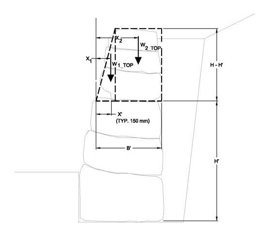
Figure 42. Graphic. Geometric relationships for determination of internal stability.
For a typical rockery, the average (uniform) bearing pressure exerted on the foundation soils (q) can nominally be computed as the sum of vertical forces (W + FA,V) divided by the base width, B. In reality, the application of a moment to the rockery by the retained soil results in a non- uniform pressure distribution in which the bearing pressure at the toe of the rockery is higher than at the heel. It has been widely reported for gravity retaining walls (14, 15, 17) that the resultant of all vertical forces (W + FA,V) acts at a particular distance from the toe of the wall, resulting in load eccentricity about the base of the footing. This concept can be easily extrapolated to rockeries. The distance from the point of action of the vertical resultant force to the toe of the rockery can be determined by dividing the sum of the net moments taken about the toe by the resultant force. The distance from the point of action of the resultant force to the center of the base rock is then defined as the eccentricity, e. The equation for determination of the eccentricity is presented in Figure 43.
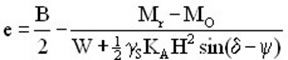
Figure 43. Equation. Determination of eccentricity, e, about the center of a base rock of width B.
If the magnitude of the eccentricity places the resultant within the middle third of the base rock, the minimum pressure at the heel of the rockery (the back of the base rock) will be such that all portions of the rock are in contact with the underlying soil. If the eccentricity falls outside the middle third of the base rock, negative bearing pressures can develop. Because the soil-rock interface cannot generally support tension, the rock could lift off or lose contact with the subgrade. To verify the resultant is within the middle third of the footing, the absolute eccentricity value (e) should be less than B/6. Provided this criterion is met, the maximum pressure imposed by the rockery can be determined using the equation presented in Figure 44.
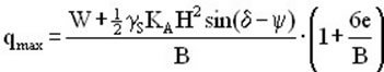
Figure 44. Equation. Determination of maximum bearing pressure (qmax) applied at the toe of the base rock.
The factor of safety against bearing capacity failure is determined by dividing the allowable bearing capacity by qmax. Various references (15, 16, 17) suggest factors of safety for bearing capacity (FSBC) in the range of 2 to 3. A factor of safety of 2.5 is commonly used for MSE walls with flexible facings, and a value as low as 2.0 can be used if settlements are checked and are tolerable. Depending on soil conditions and tolerance for settlement, it is recommended a factor of safety between 2 and 3 be used based on the judgment of the Geotechnical Engineer.
Typically, vertical surcharges at the ground surface are located behind the back face of the rockery, and, therefore, qs is not included in the calculation of qmax. However, if an anticipated surcharge, such as a construction stockpile, will act on the top of the rockery, the surcharge load should be added to the computed value of qmax when determining the factor of safety against bearing capacity failure. In the case of a construction surcharge, the use of a reduced FSBC for short-term (temporary) loading conditions may be appropriate.
In some cases, the overall rockery design may be controlled by global stability considerations. This is especially true for cuts in previously placed fills or for walls with a sloping toe condition. The purpose of a global stability analysis is to check that the rockery or retained improvements will not be damaged by a slope stability failure through or below the wall facing.
Global stability analyses can be performed using most commercially available limit equilibrium slope stability programs. Limit equilibrium analyses are performed by assuming the geometry for a potential failure plane (either a sector of a circle or a wedge-like block) and computing the ratio of the net resisting force (soil shear strength) relative to the net driving forces (soil mass, surcharge, seepage pressures, and/or seismic accelerations). This ratio is defined as the "factor of safety." For rockery analysis, the potential failure plane may pass through the face of the wall or below and behind the facing rocks. More often than not, the critical failure plane will pass beneath the toe of the rockery.
Commercial slope stability programs use algorithms to check multiple failure plane geometries and the lowest factor of safety computed for a given combination of slope geometry and strength parameters yields the critical slip surface. For a global failure to occur, the resisting forces are less than or equal to the driving forces; that is, the factor of safety is around 1.0. For static slope stability analyses, a minimum factor of safety of 1.5 is typically considered. For highway projects, it may be feasible to lower this factor of safety to 1.3; this determination can be made on a case-by-case basis by the Geotechnical Engineer.
As part of the project geotechnical investigation, the Geotechnical Engineer should evaluate soil and rock strength parameters to be used in the global stability analysis. The Geotechnical Engineer should carefully consider the properties used for the facing rocks in the analysis. Because the facing rocks consist of discrete blocks, they are typically very strong across the width of an individual block, but relatively weak at the frictional interface between the blocks. Use of an anisotropic strength envelop, in which the rocks are modeled using frictional parameters for near-horizontal failure planes and unconfined compressive strengths for oblique failures planes, should be considered by the Geotechnical Engineer.
If the factor of safety is less than the minimum required for static slope stability analyses, it will be necessary to lower the height of the rockery, move potential surcharges further back from the face of the wall, or reinforce the soil behind the rockery to create a MSE fill. Design considerations for MSE rockeries are discussed later in this report.
Many regions of the United States can be expected to experience periodic seismic ground shaking, which can impart additional seismic loads on rockeries. For roads and highway structures, the governing code regarding seismic design requirements is the AASHTO Standard Specifications for Highway Bridges, 17th Edition - 2002.(16) Per the AASHTO standard specifications, seismic design is required for all areas with a seismic coefficient, A, greater than 0.09. For those familiar with the Uniform Building Code (UBC), this is roughly equivalent to areas classified as Seismic Zones 2, 3 or 4.(8) However, the AASHTO and UBC criteria are not directly analogous, so the AASHTO criteria should be checked for each project.
The value of A should be interpolated from maps in Section 3.2, Division I-A of the AASHTO manual. The values read from the maps should be divided by 100, which results in a decimal percentage less than 1.0. These percentages represent probabilistic peak ground accelerations (PGAs) with a 10% probability of exceedance in 50 years, which corresponds to a return period of about 475 years. The AASHTO regulations note that if any of the following conditions exist, a more detailed seismicity evaluation may be required:
For items (a) and (b), the Geotechnical Engineer should be consulted to evaluate site seismicity and determine if supplemental seismic recommendations are warranted.
The AASHTO design criteria further rank sites into a seismic performance category (SPC) of A through D. While bridge design criteria vary depending on the SPC, for the purposes of this study, the requirements that apply to rockeries are constant for categories B, C, and D. Seismic design is not required for category A.
For the most part, design of rockeries for seismic conditions is similar to the design for static conditions. In general, the driving and resisting forces acting on the rockeries are determined and the rockery is checked for acceptable factors of safety against sliding, overturning, and bearing capacity failure. However, a seismic surcharge pressure acts on the rockery during earthquake shaking and should be considered as an additional driving force. The magnitude of this pressure is a function of the PGA, the rockery and slope geometry, and the quality of the retained soil.
The impact of the ground surface acceleration on the mass of retained soil is incorporated through the use of a pseudostatic horizontal seismic coefficient, kh. The vertical seismic coefficient, kv, is typically assumed to be zero. The value of kh is typically less than the site PGA, and represents the effective acceleration applied to the mass of retained soil and which causes the soil mass to move towards the rockery. This concept is analogous to the seismic coefficient used for pseudostatic slope stability analyses.
Published values of kh range between 0.05 and 0.2, although some researchers have suggested ranges between 0.3 to 0.5 times the site PGA.(9),18) For SPC categories B, C, and D, AASHTO recommends kh be taken as 0.5A for gravity retaining structures. This value is expected to result in lateral rockery movement of about 250A mm (10A in) for "gravity" rockeries. The value of kh is different for rockery-faced MSE, as discussed later in this chapter.
In accordance with the procedure developed by Mononobe-Okabe, the total thrust acting on the back of the rockery during an earthquake consists of the static rockery load (FA) plus the seismic pressure increment (Δ FAE). Δ FAE is difficult to compute directly, and textbooks( (14, 15) recommend Δ FAE be computed by subtracting FA from the total force (FAE) acting on the rockery (Δ FAE = FAE - FA). The equations required to compute the total thrust on the rockery (FAE) are presented in Figures 45, 46, and 47. The value of Δ FAE can also be estimated with reasonable accuracy as 0.5(0.75kh)gSH2.(19)
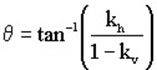
Figure 45. Equation. Determination of the term θ for computation of KAE by the Mononobe-Okabe procedure.
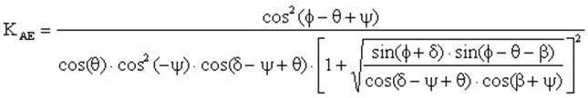
Figure 46. Equation. Determination of term KAE in accordance with the Mononobe-Okabe procedure.
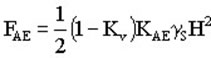
Figure 47. Equation. Determination of total thrust (seismic plus static) on rockery in accordance with the Mononobe-Okabe procedure.
In accordance with the Mononobe-Okabe procedure, Δ FAE is represented by an inverted triangular pressure distribution with the maximum value near the top of the rockery, and a resultant acting at a point 0.6H above the base of the rockery. As discussed previously, the resultant for a static equivalent fluid weight soil pressure distribution acts at a point H/3 above the base of the rockery. It follows, then, that the overall resultant for FAE acts at a point somewhere between the resultants for the static and seismic pressure distributions. An equation for the determination of the exact liner of action of FAE is presented in Figure 48.
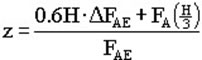
Figure 48. Equation. Vertical distance (z) from the base of the rockery to the point of application of FAE along the back of the rockery.
Once the seismic forces have been determined, it is necessary to check that external overturning, sliding, and bearing capacity are satisfied for seismic conditions. The equations are similar to those described previously except that the seismic pressure increment (Δ FAE) and the inertial force on the rockery itself (khW) must be included. Figures 49 through 54 present the equations for determining the seismic driving and resisting forces for overturning, sliding, and bearing capacity. For the overturning equation, the inertial force acts horizontally, and therefore, the vertical moment arm of the mass centroid (y) must be determined to properly estimate the moment about the base of the rockery. Alternatively, the rockery can be broken into components and individual moments for each section can be computed, as is shown previously in Figure 33.
![]()
Figure 49. Equation. Determining overturning moment for seismic conditions.
![]()
Figure 50. Equation. Determining resisting moment for seismic conditions.
![]()
Figure 51. Equation. Determining horizontal driving force to check sliding for seismic conditions.
![]()
Figure 52. Equation. Determining horizontal resisting force to check sliding for seismic conditions.
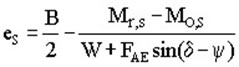
Figure 53. Equation. Determining eccentricity under seismic conditions.
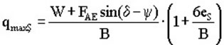
Figure 54. Equation. Determining maximum applied bearing pressure under seismic conditions.
For seismic conditions, factors of safety of at least 1.5 and 1.125 should be used to check seismic overturning and sliding potential, respectively. For bearing capacity, the factor of safety may be taken as 75% of that used to determine the static bearing capacity.
The foregoing presents a general seismic design procedure for rockeries in accordance with AASHTO guidelines and standard design methodology. However, these analyses are likely to result in large, potentially uneconomical base widths for sites with high seismic activity and ground accelerations. One way to reduce base rock sizes in zones of high seismic activity is to use seismic analyses that account for the effects of seismic deformations in the determination of kh, such as that developed by Richard and Elms. (10) This approach may be more appropriate for evaluating the seismic stability of gravity retaining structures such as rockeries. At the current time, however, this procedure is not reflected in current codes. An overview of the Richards and Elms approach is presented in Appendix A.
Wherever global stability is checked for static conditions it should also be checked for seismic conditions. A minimum factor of safety of 1.1 should be used for seismic conditions. Depending on the results of the seismic slope stability analysis, a deformation analysis may also be required to check that estimated upslope movements are acceptable where upslope improvements exist or are planned.
For the seismic analysis, a traditional pseudostatic analysis using a horizontal seismic coefficient (kh) is usually appropriate. Typically, kh is taken to be about one-third to one-half of the site PGA. Additional guidance regarding selection of kh in regions of high seismicity is presented in California Department of Conservation, Division of Mines and Geology Special Publication 117.(18)
Up to this point, the design discussion has focused on gravity rockeries retaining soil or rock. The practical limit on gravity rockeries in fill conditions is about 3.7 m (12 ft). In cut conditions, it is recommended the maximum single-tier rockery height be limited to about 4.6 m (15 ft). Rockeries exceeding these heights often require a backfill reinforced with geosynthetics to create an MSE fill or that the back cut be stabilized using a permanent retaining system, such as soil nails. Alternatively, rockeries taller than 4.6 m (15 ft) can be separated into two or more tiered rockeries.
The MSE fills may be near vertical (an MSE wall) or laid back (a reinforced soil slope, RSS). In the case of an MSE wall, the rockery would serve primarily as a protecting rockery, but would look similar to a retaining rockery. For the RSS condition, the rockery would clearly serve as a protecting rockery.
A design and construction guidelines manual for MSE and RSS, titled Mechanically Stabilized Earth Walls and Reinforced Soil Slopes, Design and Construction Guidelines, has already been published by the FHWA.(20) Therefore, recommendations regarding design and construction of these reinforced soil structures will not be repeated in this study and the reader is urged to review the MSE manual for detailed design guidelines. However, it should be noted that for seismic design of a rockery-faced MSE, the computation of kh follows design guidelines for MSE walls and differs from that for gravity walls. Specifically, the value of kh is amplified to act at the center of mass of the facing/reinforcement and will differ from the value discussed for gravity walls above.
Because MSE structures are designed for external stability, generally without regard for the facing being used, the rockery facing provides an attractive aesthetic treatment and mainly serves as an erosion control measure. Therefore, detailed analysis and design is generally not required for the facing rocks. Typically, a prescribed base width of 0.3H to 0.5H is used, with the remainder of the rockery geometry based on the prescribed face batter and top rock width.
Although RSS structures are generally constructed in an oversteepened condition, the combination of the back slope and soil reinforcement results in relatively low lateral earth pressures being applied to the back of the rockery facing. Thus, smaller rocks are generally required for this application. The methods proposed by Gray & Sotir (4) are appropriate for design of the rockery facing under these conditions.
When MSE or RSS rockeries are constructed, global stability is an important consideration. Often, the length of the reinforcing geosynthetic is governed by global stability. Therefore, the slope stability programs used to evaluate global stability of MSE rockeries should have the capability to model geosynthetic reinforcement. The reinforcement strength used in the program should be the allowable tensile strength (Ta) rather than the Long Term Design Strength (LTDS). The LTDS is computed by dividing the ultimate tensile strength of the geosynthetic reinforcement by reduction factors to account for long-term creep, installation damage, and durability/aging. To compute Ta, the LTDS should be divided by and appropriate factor of safety, typically assumed to be 1.5.
The above discussions apply for any case in which rockery is used as a facing element rather than a structural element. A similar example is that of a soil nail wall with rockery facing, as shown in Figure 21.
Another example would be the case of a hybrid system, such as a Shored Mechanically Stabilized Earth (SMSE) wall. For this system, the slope is generally retained using a permanent shoring system, such as soil nails. Then, a narrow fill is placed in front of the shoring system and facing with a segmental facing element, such as rockery. This type of system is advantageous when adding lanes to the outboard face of an existing slope.
The narrow wedge of fill placed in front of the soil nail wall applies some lateral earth pressure to the back of the facing element, which in this case would be a rockery. Thus, the required rockery design would be somewhat smaller than for the retaining rockery but larger than for a protecting rockery. In some cases, short geosynthetic reinforcement is also required within the narrow wedge of fill. Although further discussion is outside the purview of this report, additional recommendations for SMSE design can be obtained from the FHWA Shored Mechanically Stabilized Earth (SMSE) Wall Systems Design Guidelines manual. (21)
In some cases, it is necessary to tier rockeries for design or aesthetic reasons, or to reduce single- tier heights for rockeries that would otherwise exceed 4.6 m (15 ft). (5; SAGE, unpublished) While rockeries taller than 4.6 m (15 ft) have been constructed the Pacific Northwest, it is more common to tier rockeries exceeding this height. In many cases, the use of tiers is also more visually appealing and less imposing than a single, tall rockery.
Design concepts for tiered rockeries are similar to those previously discussed for gravity rockeries or rockery-faced MSE. For the lower tier, the design must include any surcharge loads imposed by the upper-tier rockery. The surcharge load can be estimated using chart solutions, elastic half-space estimates, or commercially available computer programs. For fill conditions, the lower tier often consists of an MSE rockery unless relatively short heights are constructed.
Assuming the upper rockery is set back at least 1.6 m (6 ft) from the back of the lower tier rockery, it can generally be designed as a single-tier rockery; that is, the lower tier does not materially impact the design of the upper tier rockery. However, estimated settlements should be calculated, particularly if thick fills are constructed beneath the upper tier. In addition, the global stability analyses performed for the tiered system should consider the geometric relationship between the rockery tiers; namely, they should be analyzed as a group. It may be necessary to reinforce the upper tier with geogrid in order to satisfy global stability requirements.
One important consideration for the construction of a rockery the Design Engineer can easily overlook is the space required to construct the rockery. Because the base rocks can be on the order of 0.6 to 2.5 m (2 to 8 ft) wide, rockeries are not well suited for narrow spaces or roadway shoulders that are tightly constrained in the lateral direction. The grading and layout plans should show, to scale, the anticipated width of the rockery facing and the relationship to the overall site geometry.
Another important consideration is the potential to form "ski slopes" or "launch ramps" from the constructed rockery. This condition occurs when a rockery is constructed with a sloping toe and improvements are proposed at the toe of the slope. If a cap rock were to become dislodged, either by acts of nature or acts of man, the rock could roll down the slope and damage downslope improvements. Where this condition exists, the Design Engineer should consider an alternate site layout that reduces the potential for dislodged rocks to roll downslope. Once example would be to construct a wide, flat bench in front of the rockery and prevent rocks from rolling downhill. If there is insufficient space for a flat bench, then it may be necessary to specify that all cap rocks be grouted in place to prevent them from becoming dislodged.
The design of a rockery that resists static and seismic earth pressures and lateral pressure surcharges is analogous to the design of a concrete gravity retaining wall. Gravity rockeries can generally be constructed up to 3.7 m (12 ft) tall in fill conditions without geogrid reinforcement, and up to 4.6 m (15 ft) as a facing for an MSE fill. Regardless, a maximum single-tier height of 4.6m (15 ft) should be used in cut or fill conditions. The lateral pressures acting on the back of the rockery should be determined, and the rockery checked for an adequate factor of safety against sliding, overturning, and bearing capacity failure. The factors of safety presented in Table 8 are recommended when performing rockery analyses.
| Mode of Failure | Static Factors of Safety | Seismic Factor of Safety |
|---|---|---|
| Sliding | 1.5 | 1.1 |
| Overturning | 2.0 | 1.5 |
| Bearing | 2.0 to 3.0 | 1.5 to 2.0 |
| Global stability | 1.3 (Highways)
1.5 (Other sites) |
1.1 (a) |
Notes:
(a) A deformation analysis may also be required.
Stay up to date
Sign up for announcements on grant opportunities, training, and webinars.