Previous Chapter « Table of Contents » Next Chapter
The use of dry stacked rocks to build walls is one of the earliest construction technologies used by man. It is doubtful that any early examples of rock construction were "designed," other than by trial and error, to produce a structure that was useful for a period of time acceptable to the builder. As a result, rockeries that survive today are only those that, by chance or through the experience of the builder, have certain characteristics that have allowed them to stand the test of time. These characteristics might include the use of large rock-mass-to-rockery-height ratios, tabular rock shapes, and well-drained retained materials.
One of the earliest surviving examples of a dry stacked wall is known as Hadrian's Wall, which is shown in Figure 3. Built in 122 A.D. by the Roman Emperor Hadrian, the wall served as a fortification against invasion by "barbarians." The wall is 6 m (20 ft) ta
d 3 m (10 ft) wide, and stretches 117.5 km (73 mi) across the southern border of what is now Scotland. (About Scotland, unpublished Internet reference) The wall generally does not retain soil or protect a soil slope, and, therefore, is not directly analogous to rockery design or performance. Nevertheless, it is an example of the durability and permanence of historic mortarless rock construction.
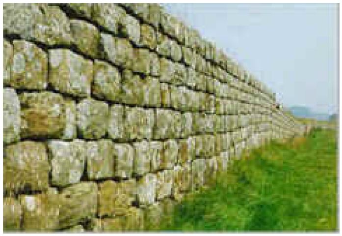
Figure 3. Photograph. Hadrian's Wall, Scotland.
View larger version of Figure 3.
Similarly, dry-stacked stone construction was used for the construction of the city of Great Zimbabwe in Zimbabwe ca. 1200 A.D. The city, which is thought to be the ruling city of the Queen of Sheba, has many surviving structures constructed of brick-sized, unmortared blocks.
The largest structure at the site, the Great Enclosure, is the largest ancient structure in Africa south of the pyramids in the Sahara Desert. The building has a circumference of about 255 m (840 ft), 10-m-high (33-ft-high) walls, and a maximum wall thickness of about 5 m (17 ft). It is estimated that about one million blocks were used to construct the Great Enclosure. (Global Heritage Fund, unpublished Internet reference)
Another example of early rock construction is the dry stacked rock walls and structures constructed by the Incas at Machu Picchu in Peru, as shown in Figure 4. Constructed between 1460 and 1470 A.D., the construction consists of tightly fitting blocks stacked without mortar. It is reported that the joints were tool finished, and although some blocks have as many as 30 "corners," the joints are so tight that a knife blade cannot be forced between the rocks. (University of Minnesota, Mankato, unpublished Internet reference) Many of these rock structures act as retaining walls. The structures were constructed using local rock materials and many blend into adjacent rock outcrops or underlying rock cliffs. In several cases, natural water features, such as springs, flow seamlessly from native rock through rockery-supported flumes.
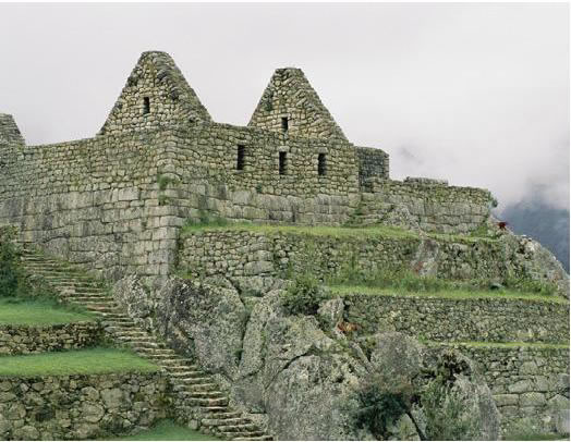
Figure 4. Photograph. Rockery construction at Machu Picchu, Peru.
View larger version of Figure 4.
Historically, dry stacked rock walls have also been constructed in rural portions of the United States. As early as the 1700s, short rock walls were used to delineate property lines in the northeastern United States. During the nineteenth century, rockeries were also constructed in the western states, often by immigrant labor. Chinese laborers reportedly constructed numerous rockeries in California during the later stages of the gold rush in the late 1800s. Many of these walls remain, particularly along railways and historic canals crisscrossing the Sierra Nevada mountain range. One example of this type of rockery is shown in Figure 5, which supported a flume for hydraulic mining outside of La Grange, California. The rockery is approximately 9.1 m (30 ft) tall and appears to have an overall width of less than 3 m (10 ft). While small areas at the flanks of the rockery have begun to deteriorate due to erosion, the majority of the rockery is still in good condition.
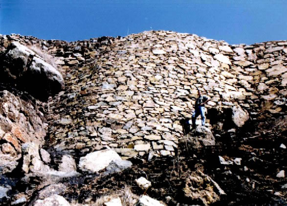
Figure 5. Photograph. Approximately 9.1-m-tall (30-ft-tall) rockery outside La Grange, California, dating from the late 1800s.
View larger version of Figure 5.
The design of rockeries appears to have been an art rather than a science, with most rockery construction based on a trial-and-error process, until sometime in the 1960s or 1970s. About this time, suitable equipment and materials became available in the northwestern portion of the United States to produce rockeries economically and dependably. These rockeries began to routinely feature tabular, tightly placed stones of adequate size to resist destabilizing forces. In addition, wall designs began to specify that crushed rock infill material be used behind the rock facing to provide high-strength backfill material and adequate drainage. These construction materials continue to be specified for current-day rockeries and are consistently observed when reviewing historical rockeries that have lasted for a hundred years or more.
Another innovation in rockery construction was the use of hydraulic construction equipment with the capability to grasp individual rocks and set them accurately within the rockery matrix, which helped speed construction. Furthermore, blasted and crushed rock with aesthetically pleasing characteristics has increased in commercial availability. When combined, these factors have all contributed greatly to the economy, popularity, and dependability of rockeries used for commercial construction in recent years.
However, while certain rockery components appear to be common to most modern rockeries, dimensioning, specifying, and engineering rockeries is an evolving process that can vary significantly between designers. The remainder of this chapter presents design and specification similarities and differences found between the different designers and governmental entities studied.
The U.S. Department of Agriculture, Bureau of Public Roads showed typical rockery sections on their plans for the Clifton-Springerville Road in the Apache Nation Forest in Arizona,(unpublished, untitled drawing) which demonstrates rockeries were being constructed by some departments within the Federal government as early as 1918. On this project, "dry rubble walls" were apparently used as headwalls at pipe outfalls. The headwalls, which appear to vary between 990 and 1,600 mm (39 and 63 in) in height, have minimum base widths of 530 to 760 mm (21 to 30 in) and top widths of 380 to 460 mm (15 to 18 in). Details are also provided for a rockery that apparently retains a fill slope with an inclination of 1V:1.5H. The detail for the rockery simply specifies a design height "H," a base width of "H/2," and a minimum dimension at the top of the rockery of 600 mm (2 ft).
More recently, rockeries were designed and constructed by the FHWA for the Guanella Pass Road project in the Pike and Arapaho National Forests in Colorado.(6, 7) The rockeries for Guanella Pass were specified with a maximum height of 3.5 m (11.5 ft). Tiered rockeries were limited to 3 m (10 ft) per tier. Specific rockery dimensions were described on the plans using the following design parameters, where H is the design height as measured from the bottom of the base rock (rock that bears on the soil subgrade) to the top of the cap rock (uppermost rock in the rockery, usually flush with the retained surface):
Typical wall details and schedules for the Guanella Pass bid documents are presented as Figures 6 and 7. (6) The schedule provides man-rock designations for each rockery lift with regard to overall rockery height. Man-rock sizes are also provided. An example of a completed rockery for the Guanella Pass project is presented as Figure 8.
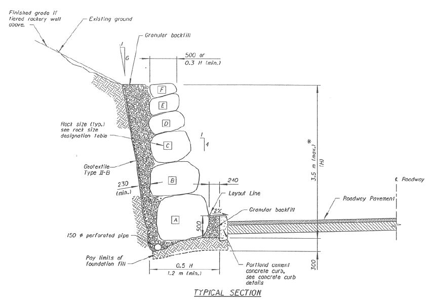
Figure 6. Graphic. Typical rockery section from Guanella Pass bid documents.
View larger version of Figure 6.
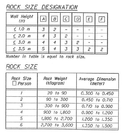
Figure 7. Graphic. Typical rockery schedule from Guanella Pass bid documents.
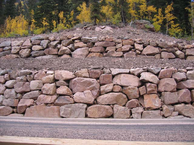
Figure 8. Photograph. Completed rockery for Guanella Pass Road, Colorado, 2005.
View larger version of Figure 8.
Rockery design recommendations were also identified in a Retaining Wall Design Guide published by United States Department of Agriculture, Forest Service, in 1994 (Report No. FHWA-FLP-94-006). The design guide references reports and figures by Gifford & Kirkland(5) and ARC (1) as the primary design aids. Rockeries are described as providing limited resistance to lateral earth pressures, and to be used primarily for erosion protection. The maximum recommended height for rockeries is 4.6 m (15 ft). For rockeries retaining fill, it is recommended that the fill consist of Mechanically Stabilized Earth (MSE) for heights over 2.4 m (8 ft).
Rockeries have been constructed in the Pacific Northwest for at least the last four decades, as evidenced by Gifford and Kirkland, (5) who describe a robust rockery design practice in 1978. Because of the long history of construction in the area, many of the local municipalities have developed detailed guidelines for construction specific to rockeries. These guidelines generally include prescriptive methods for design and construction of rockeries less than 1.8 m (6 ft) tall. Engineered design is generally required for rockeries that exceed a height of 1.8 m (6 ft), and in some cases, less. Prescriptive design parameters were obtained for the City of Seattle, Washington; City of Brier, Washington; and Mason County, Washington. The prescriptive design parameters for these municipalities are summarized later in this chapter. Portions of the guidelines have also been adopted by the City of Sparks, Nevada, and the City of Knoxville, Tennessee.
The rockery construction profession also developed guidelines for rockery construction. Based on experiences in the Pacific Northwest, these guidelines, published by the ARC,(1) provide guidance regarding bidding practices, rockery layout, drainage, and the role of the geotechnical engineer. The guidelines also state that rockeries are generally used as erosion control structures; where they retain lateral earth pressures, they should be designed by a geotechnical engineer.
One significant innovation to come out of the Pacific Northwest has been the use of a zone of crushed rock behind the rockery. In addition to providing a dedicated drainage layer, the crushed rock provides a zone of material with a high natural friction angle, and, thus, a relatively low active earth pressure coefficient, KA. When the crushed rock comprises a significant percentage of the backfilled zone, the high strength of the crushed rocks helps reduce the lateral earth pressure on the rockery and helps stabilize the rockery system.
Because rockeries have been designed and constructed for several decades in the Pacific Northwest, many of the published references located for this study originate from this area. The information obtained from these studies follows.
In their paper Uses and Abuses of Rockeries, Gifford and Kirkland (5) provide generally prescriptive design standards for rockeries, but with much more detail and for taller rockery heights than the municipal recommendations discussed previously. When Gifford and Kirkland prepared their report in 1978, rockeries were seeing increasing use as retaining structures. However, the paper suggests Gifford and Kirkland believed rockeries were an inferior retaining structure relative to other engineered structures, and that they believed the best use of rockeries was to protect otherwise stable slopes. Specifically, Gifford and Kirkland commented that:
Gifford and Kirkland reference an unpublished report prepared by A. J. Hendron, Jr. in 1960. The original report by Hendron could not be located. Per Gifford and Kirkland, Hendron determined the stability of rockeries is controlled by overturning, rather than inter-rock or global sliding, and that the rockery stability is highly dependent on the rockery face inclination. The research included development of a design chart, as shown in Figure 9, which presents "critical" height-to-base-width (H/B) ratios for prescribed soil conditions based on overturning stability. The nature of the term "critical" is not discussed in the Gifford and Kirkland paper, and because the original work by Hendron could not be located, it is not clear if the "critical" value represents a factor of safety of 1.0 or an "allowable" value. For the purposes of this study, it has been assumed "critical" implies failure is imminent, yielding a factor of safety of 1.0.
The chart provides design curves for both well-constructed rockeries (WCR) and poorly constructed rockeries (PCR). This distinction was made to account for assumptions in the analyses regarding the point about which rotation is assumed to occur. The point of rotation is assumed to be at the midpoint of the base of the rockery for PCRs, whereas it is near the face of the rockery for WCRs. Gifford and Kirkland recommended that because this subjective measure of workmanship was difficult to evaluate, the curves for PCRs should be used for design.
The chart is used by determining the wall height (H), internal soil friction angle (φ), and slope inclination (i). Because the chart was constructed assuming a value of 17.6 kN/m3 (110 pcf) for the soil unit weight (γ), the chart should be regenerated, using the equations shown on Figure 9, for larger values of γ as a larger lateral earth pressure will be imposed on the rockery. The values of i and φ are then used, along with the PCR curve, to determine the critical H/B ratio. This ratio is in turn used to determine the minimum average base rock width (B).
For example, given a rockery height of 3 m (10 ft), a slope inclination of 80 degrees, and a soil friction angle of 30 degrees, the critical H/B ratio read from the Hendron chart is about 4. Therefore, the critical base width required to satisfy minimum overturning stability requirements is 0.75 m (2.5 ft). If the friction angle is increased to 35 degrees, H/B increases to about 5.5 and β decreases to about 0.5 m (1.6 ft). In practice, larger values would likely be used for design because these are "critical" values and likely represent a factor of safety of 1.0. Alternatively, if β is known, the chart can be used to determine the critical height, above which the factor of safety is less than 1.0. For example, given a base width of 1.2 m (4 ft), a slope inclination of 85 degrees, and a friction angle of 30 degrees, the H/B ratio is 2 and the maximum (critical) rockery height is about 2.4m (8 ft).
The chart that has been provided (as originally published in Gifford and Kirkland) is valid for the values of φ between 30 and 35 degrees, and a value of γ of about 1.7 kN/m3 (110 pcf). For other values, the user should generate new curves using the equations shown in Figure 9.
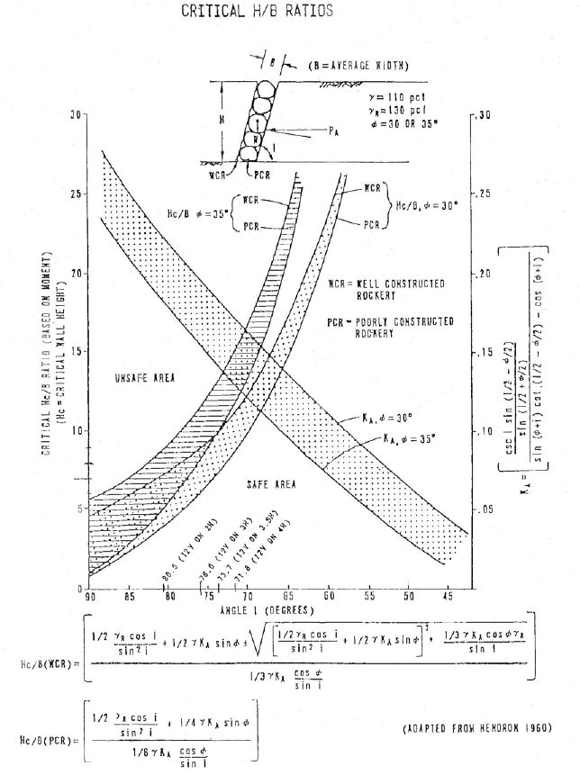
Figure 9. Chart. Critical height-to-base-width (H/B) ratios for poorly constructed rockeries (PCRs) and well-constructed rockeries (WCRs), after Hendron.
View larger version of Figure 9.
Gifford and Kirkland indicated that the maximum rockery base thickness (B) they have observed is about 1.2 m (4 ft), with an average rockery thickness of about 0.9 m (3 ft). In addition, most rockeries they observed had face batters between 12V:1H to 12V:4H ("i" values between 85 and 72 degrees, respectively). For a reasonable range of retained soil friction angle (φ) and using the Hendron chart (PCR curves, Figure 9), Gifford and Kirkland concluded the theoretical maximum rockery height is between 3.7 and 11 m (12 and 36 ft).
However, Gifford and Kirkland also noted that most failures observed through their practice occurred to rockeries constructed to heights exceeding 4.6 m (15 ft), and, therefore, 4.6 m (15 ft) is a reasonable maximum single-tier design height. Furthermore, where rockery failures have been observed, they indicated that it generally required more rocks to repair a failed rockery than were originally required to construct it, suggesting that failures are highly dependent on the original density (packing) of the rocks and that a denser packing results in a more stable rockery.
An interesting statement in the Gifford and Kirkland report is that they contend most owners understand there is a "lower standard of engineering" for rockeries than for other engineered retaining structures, such as cast-in-place or concrete masonry unit walls, and that rockery failure is a possibility. However, this potential for failure is outweighed by construction cost savings. Where failures have been observed, they listed the six most common causes (additional details were not provided by Gifford and Kirkland):
They recommended periodic maintenance and inspection of rockeries so that remedial measures could be taken if the potential for failure is observed.
In 1990, Hemphill Consulting Engineers (Hemphill) of Bellevue, Washington, presented analytical methods for rockery design in a report titled The Engineering Method for Rockery Design.(unpublished, 1990) Hemphill noted that rockeries can function adequately as retaining walls if they are properly designed. However, many contractors believe they must "design" rockeries in the field through proper placement and field fitting because the plans and specifications provided are "so ambiguous as to be nearly useless." Hemphill cites the widespread use of the man rock designation as one problematic feature because the dimensions of the rocks are poorly defined and often vary between municipalities. However, at the time of his report, the use of man rock designations appears to have been standard of practice in the area.
For the Hemphill procedure, the active earth pressure on the back of the rockery is computed in 0.3-m (1-ft) increments, beginning at the top of the rockery and ending at the base. For each increment, a rock width is computed that satisfies factor of safety requirements for both inter- rock sliding and overturning. The computations account for the weight of the trial rock at the increment being checked, as well as the weights of all overlying rocks. The overturning moment due to the lateral earth pressure is then computed about the toe of the rock at each level. The width of the rock is varied until the desired factor of safety with respect to both sliding and overturning is computed. Below finish grade, the minimum rock width is computed by checking for adequate factor of safety to resist sliding using both friction on the bottom of the base rock and passive pressure against the face of the rockery. A sample calculation, excerpted from the Hemphill report, is shown in Figure 10.
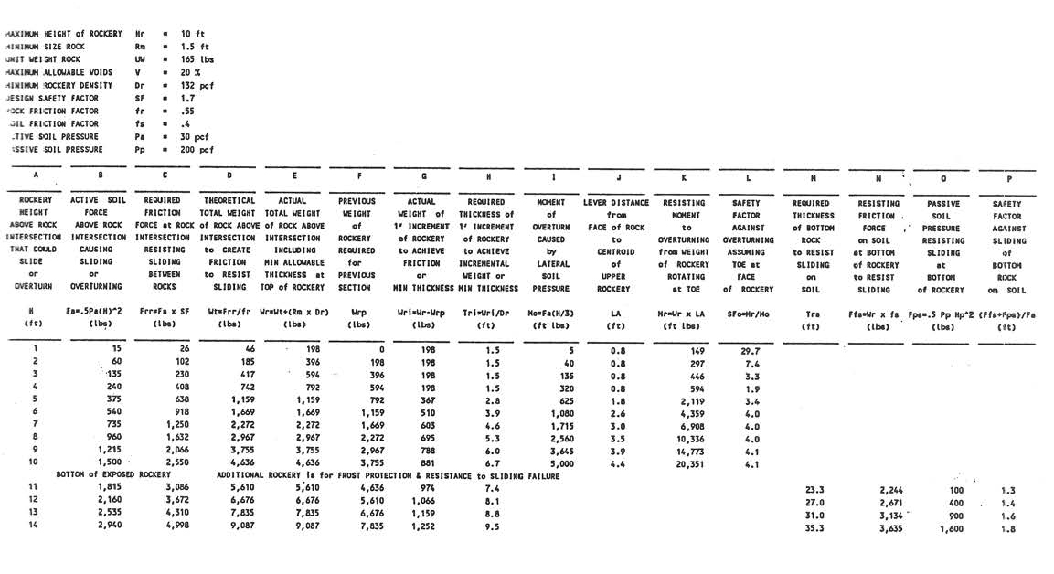
Figure 10. Graphic. Sample calculation from the Hemphill report demonstrating application of the Hemphill design method.
View larger version of Figure 10.
Hemphill suggests the factors of safety against overturning and sliding used in the analyses be selected based on the degree of control and level of observation the design engineer will have during construction:
One topic noticeably absent from both the Gifford and Kirkland and Hemphill papers is seismic design. However, the Pacific Northwest is a seismically active area, and it is expected that rockeries constructed in the region will likely be subjected to seismically-induced ground shaking during their useful life. The Nisqually earthquake, which occurred on February 28, 2001 near Olympia, Washington, provided a case history to evaluate rockery performance during a seismic event.
The earthquake had a moment magnitude (Mw) of 6.8 and was centered approximately 17.7 km (11 mi) northeast of Olympia, Washington. Recorded peak ground accelerations (PGAs) ranged from 0.1 to 0.2 times gravity (g). (Pacific Northwest Seismograph Network, unpublished) On March 8, 2001, a reconnaissance of five sites with completed rockeries was performed to document their properties and conditions. This reconnaissance was performed by Steven H. Sanders of Sanders & Associates Geostructural Engineering (SAGE) and Gordie McCarty of Parsons Brothers Rockery Retaining Walls. A summary of their observations is presented as Table 2. Photographs from each of the five sites visited are presented as Figures 11 through 15.
No rockery failures were observed during the reconnaissance, and the overall conclusion was that the rockeries performed well under the low to moderate PGAs experienced during the earthquake. The rockeries observed provided a fairly wide spectrum of rockery heights, base widths, and quality of construction.
| Observed Properties | Site 1 | Site 2 | Site 3 | Site 4 | Site 5 |
|---|---|---|---|---|---|
| Distance from Epicenter, km | 32.2 | 32.2 | 17.7 | 14.5 | 25.8 |
| Estimated PGA, g | 0.15 | 0.1 | 0.15 | 0.12 | 0.1 |
| Estimated Construction Completion, year | 2001
(ongoing) |
1980s to 1995
(3 walls) |
N/A | N/A | N/A |
| Rockery Height, m | 3 | 2.7 to 7.3 (tiered portions) | 1.2 | 2.1 - 2.4 | 7.6 |
| Rockery Length, m | 45.7 | N/A | N/A | N/A | N/A |
| Base Rock Width, m | 1.2 - 1.5 | 1.2 - 1.5 | 0.6 - 0.9 | 0.6 - 0.9 | 1.5 - 2 |
| Base Width, % of H | 0.4H - 0.5H | 0.4H - 0.7H | 0.6H - 0.75H | 0.25H - 0.4H | 0.25H |
| Cap Rock Width, m | 0.3 - 0.9 | 0.3 - 0.6 | N/A | 0.6 - 0.9 | 1.2 - 1.5 |
| Backfill | Native silty sand with 50- to 200-mm crushed rock | Crushed rock | Soil | Crushed rock | Crushed rock
(50 to 100 mm) |
| Foundation | Silty sand | N/A | N/A | N/A | Silty sand |
| Apparent Construction Quality | Fair | Poor to fair | Fair | Good | Fair; lots of voids |
| Nearby Damage (unrelated to rockery) | None | None | Cracks to Capital Building dome | None | None |
| Observed Rockery Damage | None | (a) | (b) | (c) | None |
Notes:
(a) Some bulging noted from foundation movement, does not appear related to the earthquake.
(b) Some static movement (shifting) appears to have occurred in the past.
(c) Horizontal separation between rocks at end of rockery; may be caused by construction or earthquake.
N/A = Data not recorded, not applicable, or unknown.
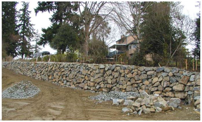
Figure 11. Photograph. Single-tier, 3-m (10-ft) rockery, Military Road at Enchanted Parkway, Federal Way, Washington (Site 1).
View larger version of Figure 11.
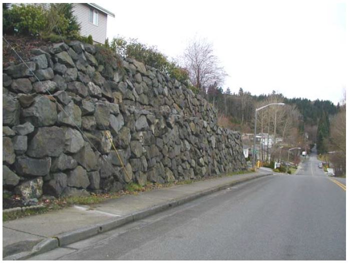
Figure 12. Photograph. Two-tier, 7.3-m (24-ft) rockery, 15th Avenue at 12th Street, Puyallup, Washington (Site 2), with guy wire anchored at base of rockery.
View larger version of Figure 12.
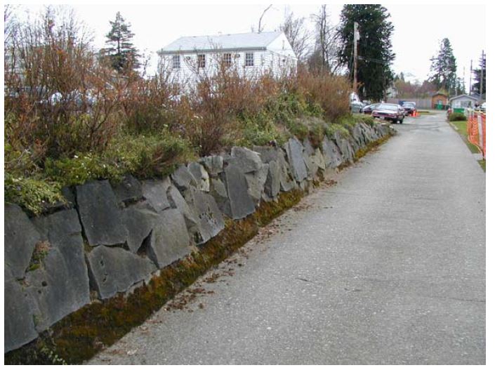
Figure 13. Photograph. Single-tier, 1.2-m (4-ft) rockery near state capital building, Olympia, Washington (Site 3).
View larger version of Figure 13.
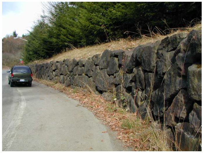
Figure 14. Photograph. Single-tier, 2.4-m (8-ft) rockery, Nisqually National Wildlife Refuge, Washington (Site 4).
View larger version of Figure 14.
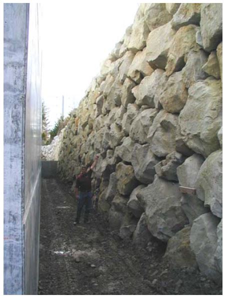
Figure 15. Photograph. Single-tier, 7.6-m (25-ft) rockery in Tacoma, Washington (Site 5).
View larger version of Figure 15.
One objective of this study was to identify scholarly references, juried papers, or textbooks regarding rockery design and construction. Unfortunately, very few of these types of documents were uncovered. With the exception of Gifford and Kirkland(5) and the Forest Service design guide, most of the references previously cited have been either unpublished or contained within city or county municipal codes.
One exception is Biotechnical and Soil Bioengineering Slope Stabilization, a textbook written by Gray & Sotir. (4) Rockeries are discussed in Chapter 5 of the textbook, although they are referred to as "rock breast walls." Gray & Sotir describe the typical rockery as 3 m (10 ft) high or less, constructed of courses of rocks that are a single rock-width wide, and within which upper rocks should rest on two lower rocks with at least three-point bearing. Angular rocks are the preferred construction material. They also note rockeries should be primarily used to "defend the toe of the slope and to prevent slope damage by erosion…"
Gray & Sotir conclude rockery stability is governed by the rockery face batter angle and H/B ratio, which is consistent with the previous references discussed. They believe H/B should typically not exceed 3. Furthermore, they indicate that typical base rock widths are about 0.6 m (2 ft), and, therefore, typically rockery heights are about 1.8 m (6 ft).
The Gray & Sotir text provides a closed form solution that can be used to evaluate rockery stability under the proper conditions. Because, like previous researchers, they concluded stability is typically governed by overturning (in lieu of inter-rock shear and bulging), their equations were developed to solve for overturning stability. Figures 16 and 17 present the Gray & Sotir equations that can be used to compute H/B ratios as a function of the properties of the retained soil, facing rocks, and desired overturning factor of safety. It should be noted that there is a minor error in the equations presented in the textbook that has been corrected in the equations presented throughout this report. The corrected equations have been confirmed as correct by Professor Gray (personal communication).
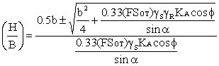
Figure 16. Equation. Height-to-base-width (H/B) as a function of factor of safety, rockery inclination, backslope inclination, and soil and rock properties, from Gray & Sotir.
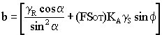
Figure 17. Equation. Definition of the term "b" in Figure 16.
The equations presented in Figures 16 and 17 were developed assuming angular rocks; modifications are required for rounded rocks. These equations also neglect backfill cohesion, and, therefore, may be conservative for some circumstances. The equations indirectly address backslope inclination through the use of the active earth pressure coefficient, KA.
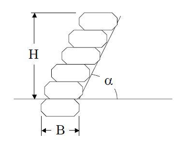
Figure 18. Graphic. Assumed geometric relationships to be used for equations shown in Figures 16 and 17.
In addition to the equations provided above, Gray & Sotir also provide a schematic rockery diagram with several rules of thumb, including:
Many of these recommendations are similar to those previously discussed, including the minimum embedment, rockery drainage, and maximum backslope inclination.
Of additional interest is that much of the early work for the Gray & Sotir textbook was originally published without the equations presented in Figures 16 and 17 in the United States Department of Agriculture, Natural Resources Conservation Service Engineering Field Handbook (Chapter 18) in October 1992. Although the Engineering Field Handbook implementation of the rockery design methods proposed by Gray & Sotir appear much less rigorous than the later textbook, it appears the Handbook is still in use by some Federal agencies.
Rockeries have been designed and constructed in northern California for about the last 10 years. Single tier rockeries are generally capable of supporting cut slopes up to about 4.6 m (15 ft) in height, whereas the maximum height of rockeries used to retain unreinforced fill is typically limited to about 3.7 m (12 ft). For fills between 3.7 and 4.6 m (12 and 15 ft), it is often necessary to reinforce the fill with geogrids to create a mechanically stabilized earth (MSE) fill and use the rockery as a facing element. MSE fills may also be required for heights less than 3.7 m (12 ft) depending on the properties of the retained soil or global stability concerns. Under these conditions, the rockeries serve as a protecting rockery because the MSE is designed to be globally stable without the facing. Protecting rockeries can also be used in conjunction with other types of earth retention systems, such as soil nails, in cut conditions. Examples of single- tier rockeries in both cut and fill conditions are presented as Figures 19 through 21.
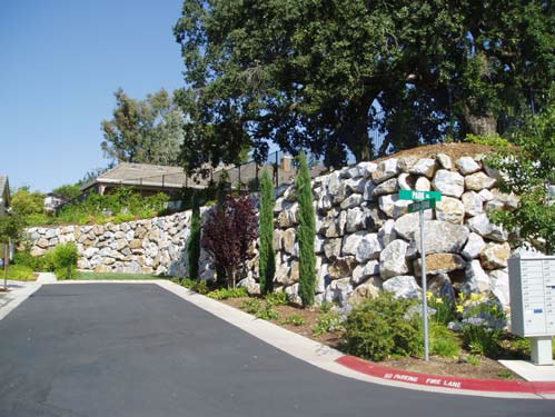
Figure 19. Photograph. Single-tier rockery constructed in cut condition, El Dorado Hills, California (2001).
View larger version of Figure 19.
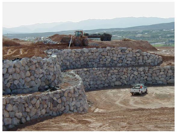
Figure 20. Photograph. "Protecting" rockery used as a facing for a 9.1-m-high (30-ft-high) MSE wall with a 5.5-m (18-ft) maximum tier height in Henderson, Nevada (2001)
View larger version of Figure 20.
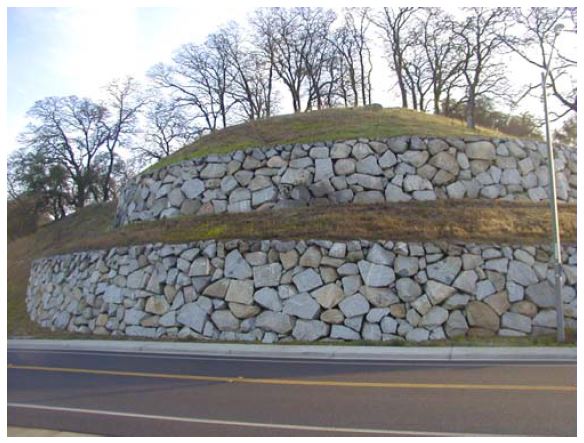
Figure 21. Photograph. "Protecting" rockery used as a facing material for a two-tier, 7.6- m-high (25-ft-high) soil-nail wall in Rocklin, California (1999).
View larger version of Figure 21.
As Figures 20 and 21 also show, rockery heights can be significantly increased through the use of tiers. The primary considerations for rockeries in tiered conditions are the surcharge posed on lower tiers by upper tiers and global stability of the overall system. Figure 22 shows another example of a three-tier, 9.1-m-high (30-ft-high) protecting rockery constructed to face an MSE fill.
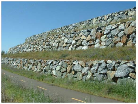
Figure 22. Photograph. Three-tier, 9.1-m-high (30-ft-high) MSE slope with protecting rockery facing, in Folsom, California (2003).
View larger version of Figure 22.
The authors (SAGE) have developed in-house analysis programs for rockery design that are based on the concepts common to conventional gravity wall design. These concepts generally follow the rational approach presented in the American Association of State Highway Transportation Officials (AASHTO) for gravity wall design. Driving forces are based on lateral earth pressures caused by the retained soil (Coulomb method) as well as any additional surcharges, such as sloped backfill or traffic. Resisting forces are based on soil-rock friction and soil bearing capacity, generally using parameters provided by the project geotechnical engineer. As recommended by the AASHTO, passive resistance at the toe of the rockery is usually neglected. The analysis method consists of assuming a base rock size and checking to determine if the overall factors of safety against bearing, overturning, and sliding are acceptable. The following static factors of safety are used:
FSOT = 2.0
FSSL = 1.5
FSBC = 3.0 (or less, if allowed by the geotechnical engineer)
Unlike some of the procedures developed in the Pacific Northwest, rockeries are specified by base width rather than through a man rock designation. The minimum base width is nominally specified as 0.5H. By specifying a base width, closed-form equations can be solved for the factors of safety listed above. Designation of a specified base width also removes some of the construction uncertainty and variability previously associated with "man rock" designations. Sizes of overlying rocks are then determined by specifying a vertical back of rockery, a 4V:1H batter for the front face of the rockery, and a minimum cap rock size.
Because the seismic activity is relatively high throughout California, the rockeries are designed for use in Uniform Building Code (UBC) Seismic Zones 3 and 4.(8) Seismic earth pressures are determined using the Mononobe-Okabe method,(9) and the potential for rockery movement due to the seismic surcharge pressure is checked using an allowable displacement method proposed by Richards and Elms (10) for gravity walls. This method computes a value of the seismic coefficient, kh, by assuming an allowable permanent rockery displacement in a manner analogous to the Newmark sliding block analysis procedure originally developed for evaluation of seismic slope stability. The computed value is typically less than the presumptive value of one-half the peak ground acceleration required by other design methodologies. The procedure consists of the following steps:
Based on review and analysis of the Richards and Elms methods, Whitman(11) concluded a factor of safety of 1.1 with respect to the required wall weight resulted in a 90% probability that actual wall movement will not exceed the tolerable displacement. The tolerable displacement is generally estimated as about 5% of the base width. Considering most base rock widths vary between 0.9 and 2.4 m (3 and 8 ft), tolerable displacements are typically about 50 to 120 mm (1.8 to 4.8 in). The significance of this method is that smaller base rocks are required for seismic design that would be required if no movement were allowed.
A key assumption in this analysis method is that the rockery can be treated as a single unit, and that gravity retaining wall design and analysis procedures can be applied to address the stability of the overall rockery system. Unlike the method proposed by Hemphill, this method assumes that proper construction of the rockery will resolve any concerns related to inter-rock stability. Specifically, inter-rock stability is addressed by specifying that the contact point between the upper and lower rocks is always within 150 mm (6 in) of the average rockery face; that is, the contact point is at, or very close to, the front of the rockery. This results in an acceptable factor of safety for inter-rock overturning, and, because inter-rock overturning has been shown to be more critical than inter-rock sliding, inter-rock sliding is also resolved. Similar to other methods described previously, several prescriptive requirements are specified for each rockery, including:
To verify that the rockeries are constructed according to these specifications, intermittent observation by an experienced engineer is required during construction of all rockeries taller than 1.8m (6 ft). Deficient construction materials or procedures can then be identified and corrected.
As evidenced by the preceding sections, the literature search performed for this study suggests that the analytical methods used for the design and evaluation of rockeries is limited and varies considerably. However, although the design methods vary, many of the general rules-of-thumb used to guide rockery design are relatively consistent. The various design procedures and rules- of-thumb are summarized (by source) in Table 3 (Prescriptive Methods) and Table 4 (Analytical Methods).
Although not shown in Table 3, none of the prescriptive methods specify minimum values for the base rock width; chinking; rock shape or angularity; or the minimum cap rock width or weight.
| Design Parameter | City of Seattle, WA (2) | City of Brier, WA(3) | City of Knoxville, TN (13) | City of Sparks, NV (unpublished) |
|---|---|---|---|---|
| Maximum height, m (ft) | 1.8(6)(a) | 1.8(6) | 1.2 (4) (a) | 1.8(6) |
| Minimum embedment, mm (in) | 300 (12) | N/A | 600 to 900 (24 to 36) |
300 (12) |
| Maximum batter | 4V:1H | N/A | 12V:1H | 4V:1H |
| Maximum backslope | 3V:8H | 1V:3H | N/A | 1V:3H |
| Rock size designation | Man rocks | N/A | Width 20 to 60 cm | Man rocks |
| Rockeries allowed in fill conditions? | No (b) | Yes | N/A | Yes (b) |
| Backdrain required? | Yes | Yes | Yes | Yes |
| Minimum backdrain thickness, mm (in) | 300 (12) | N/A | N/A | 460 (18) |
Notes:
(a) Maximum height is for prescriptive design; taller rockeries are allowed with engineered design.
(b) Not considered a retaining structure; no surcharge is allowed.
| Design Parameter | Gray & Sotir (4) | Gifford & Kirkland(5) | Hemphill (1990; unpublished) |
SAGE (unpublished) |
|---|---|---|---|---|
| Design methodology | Solve equation for height-to-base- width (H/B) ratio based on soil friction angle (φ), overturning factor of safety (FSOT), and facing geometry | Solve for critical H/B ratio based on φ and slope inclination (i) values; use poorly constructed rockery (PCR) curves | Design rockery in 0.3-m (1-ft) increments from top down; solve for FSOT above finish
grade at base of rockery, and sliding factor of safety (FSSL) for embedded portion of rockery |
Design as a gravity retaining structure; satisfy internal stability through rock placement specification; include seismic forces |
| Minimum factors of safety: | ||||
| Overturning (FSOT) | No minimum specified | 1.0 (a) | 1.5 to 2.5 (b) | 2.0 |
| Sliding (FSSL) | N/A | N/A | 1.5 to 2.5 (b) | 1.5 |
| Bearing (FSBC) | N/A | N/A | N/A | 3.0 |
| Maximum height, m (ft) | 3.0 (10) | 4.6 (15) | N/A | 4.6 (15) |
| Minimum base width | N/A | H/3 | N/A | H/2 |
| Embedment determination | Prescriptive; 300 mm (12 in) minimum | Prescriptive; 300 mm (12 in) minimum (c) | Calculated; based on FSSL | Prescriptive; 300 mm (12 in) minimum |
| Maximum face batter | 3V:1H | 4V:1H | N/A | 4V:1H |
| Maximum backslope inclination | 1V:2H | Flat | N/A | 1V:1.5H |
| Rock size designation | Width | Man rocks | Width | Width |
| Used for fill conditions | No | Possible | Yes | Yes (d) |
| Backdrain required? | Yes | Yes | Yes | Yes |
| Minimum backdrain thickness, mm (in) | 200 (8) | Varies; based on back cut | N/A | 300 (12) |
| Minimum cap rock weight, kg (lb) | N/A | N/A | N/A | 90 (200) |
| Minimum cap rock width, mm (in) | 400 (16) | N/A | 460 to 610 (16 to 24) | 400 (16) |
| Rock shape | Angular | Angular | N/A | Angular |
| Chinking required? | N/A | Yes | Yes; voids >150 mm (6 in) | Yes; voids >150 mm (6 in) |
Notes:
(a) Assumes "critical" H/B ratio is based on factor of safety of 1.0.
(b) Factor of safety varies depending on level of observation by engineer.
(c) Minimum embedment to base of rock; requires an additional 150 mm (6 in) gravel foundation layer.
(d) For rockeries in fill more than 3.7 m (12 ft) tall, used as a facing for mechanically stabilized earth (MSE).
Stay up to date
Sign up for announcements on grant opportunities, training, and webinars.