Previous Chapter « Table of Contents » Next Chapter
Preparing the road for a chemical treatment and the process followed when applying it are critical for successful performance. Different additives are applied in different ways, usually either sprayed directly onto the prepared road surface, or mixed in during regravelling or in a reworking of the surface. Spray-on applications are the most popular because they are the least expensive for initial application. However, rejuvenation frequencies are usually higher because of the limited penetration of some additives and consequently may work out to be more expensive than mix-in treatments in the longer term. Mix-in treatments are generally required if chemical treatments are being used to both reduce dust and improve all-weather passability, or as clay stabilizers, since the additive needs to be distributed through the top two inches (50 mm) of material for dust control additives and top four to six inches (100 mm to 150 mm) of material for clay stabilizers and/or improving all-weather passability. Some chlorides can be applied in pellet or flake form, which can be spread on the road surface.
The preparation of roads before applying chemical treatments generally follows standard road construction procedures and uses standard road construction and maintenance equipment.
However, standard practice is often overlooked or has been "forgotten," and consequently, sub- standard construction is accepted, which leads to less than satisfactory performance.
Magnesium chloride was the additive of choice in many areas and most applications were simple spray-on treatments. However, the level of effort afforded to road preparation and knowledge of the consequences of inadequate preparation, inappropriate application procedures, and optimizing rejuvenation intervals varied across the locations visited. On roads where mix-in treatments were used, tighter control over construction could have resulted in better long- term performance. Key problems noted included selection of lower quality aggregate (Figure 58), insufficient crown and drainage, poor compaction, spraying additives onto dry surfaces, and spraying the full dose of additive in a single pass. Many equipment operators had learned their skills from others on the job and had consequently inherited inappropriate techniques with no understanding of the consequences. Most scan tour hosts used construction specifications based on those of the state road agency. The lack of specifications and comprehensive guidelines for selecting and applying additives was repeatedly identified as an unmet need.
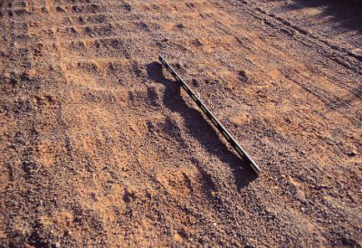
Figure 58. Photo. Poor gravel selection for treated road.
As with materials, the performance of unpaved road chemical treatments is also influenced by how well the road is prepared before application and then how appropriately it is applied. The approach recommended in this handbook advocates following conventional road construction and additive application procedures, with adjustments and additional steps to suit the specific additive being used. Road managers are encouraged to request detailed road preparation and application guidelines from additive vendors. A number of key issues are introduced in this section of the handbook, including drainage, road shape, wearing course thickness, road geometry, application rates, and application techniques. Road managers are also encouraged to employ additional information and knowledge from readily available guidelines (for example, the FHWA Gravel Roads - Maintenance and Design Manual).
Spraying dust control treatments onto unprepared roads is a waste of time and money. The dust control effect will be short lived, ride quality will not be improved, and the road will soon require some form of maintenance, which will reduce the life of the treatment (Figure 59). Prior to any spray-on application, shape the road to ensure an adequate crown is present, and then blade to provide a quality driving surface. Open drainage ways and culverts to ensure that water can be channeled away from the road during rain events. If the chemical treatment is going to be applied as part of a regravelling activity, incorporate the additive into the compaction water and mix this in with the aggregate.
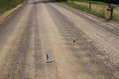
Figure 59. Photo. Chloride applied to poorly prepared road.
Good drainage is imperative for optimal performance of unpaved roads, especially in terms of all-weather passability, reducing slipperiness and erosion, and preventing potholes. Drainage includes two components.
Never shape a road when it is dry as this will loosen up sections of crust, segregate the materials, break down softer aggregates, and invariably result in a thin "biscuit" layer on the surface (Figure 63), which will break down quickly and ravel to the side, leading to rapid loss of the new crown. Instead, spray the road surface with water to bring the top two inches (50 mm) to about near optimum moisture content. This can be determined either using a microwave oven on site and comparing the moisture contents to those determined in a laboratory, or simply by doing the "squeeze" test (that is, a handful of material, when squeezed in the hand should hold the shape of a ball without exuding water [too wet, leaving a sheen of water on the skin], or crumble [too dry] when released [see Figure 64]).
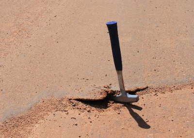
Figure 63. Photo. Effect of biscuit layer on treated surface.
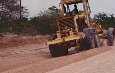
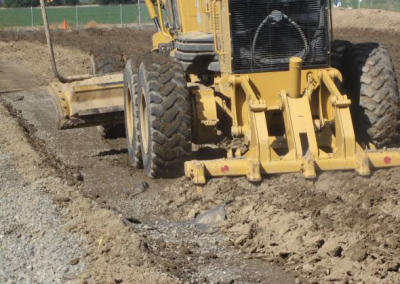
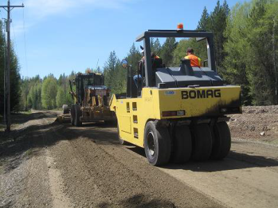
Once the material is adequately moistened, use a motor grader equipped with a slope meter or electronic grade control to achieve/maintain the required crown (typically five percent). If available, compact the road with a rubber-tire roller, smooth drum steel roller (no vibration) or even a grader-mounted roller (Figure 65) to consolidate the material and seal the surface. The grader blade should have good, new, straight edges to avoid rounding the surface.
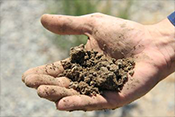
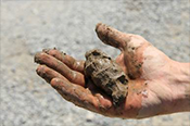
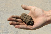
Figure 64. Photo. Squeeze test for assessing moisture content.
([a] too dry, [b] too wet, and [c] acceptable)
Material from the side drains should NOT be bladed onto the road since it is typically silt and will result in a dusty "biscuit" layer that will be displaced by traffic in a short time. Uniformity of depth of the surface material should be maintained.
A good, compacted crown will reduce the need for frequent reshaping and blading and will extend the life of a treated road.
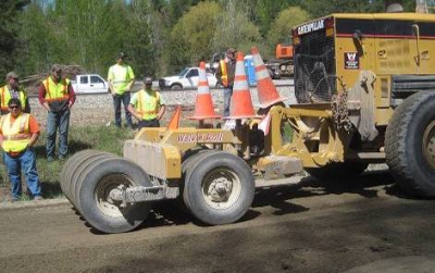
Figure 65. Photo. Grader-mounted roller.
Applying chemical treatments to unpaved roads where the surface has worn away is a waste of time and money. This is because the fines content is typically either too low or too high (remember that the fines are the "glue" that holds a wearing course together), the aggregate grading is usually poor (that is, probably more suited to base material in a sealed road than to a wearing course in an unsealed road), the subgrade is often exposed, and the road surface is often level with or below the natural ground level, which leads to drainage problems. Also, always remember that dust palliatives and surface stabilizers will not make a bad road good - they should only be used to keep a good road good.
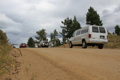
Consider importing a suitable roadway surfacing aggregate when dealing with worn surfaces. In the case of subgrade exposures, a new base and wearing course will need to be imported, while in the case of base exposures, only a new wearing course will be needed. Surface thickness of the wearing course will depend on a number of factors including available funds, height of the existing road above the natural ground level (Figure 66), and traffic volumes. A "thicker-the-better" approach is generally best because of the high labor and equipment costs associated with construction, and the need to have sufficient material to work with during routine maintenance. At a minimum, the road structure (that is, gravel material covering the natural subgrade) should be at least 12 inches (300 mm) above natural ground level, and higher in high rainfall regions and areas with weak subgrade (that is, subgrade CBR is less than five or dynamic cone penetrometer [DCP] penetration is more than 32 mm/blow). The following simple formula can be used to calculate the minimum thickness of gravel required:
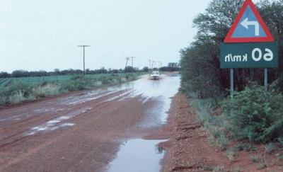
Figure 66. Photo. Road below natural ground level.
T = t + (1 + Ct / 100) x (GL x L)
Where:
T = design thickness (in inches or mm)
t = minimum thickness required for subgrade protection (e.g., 12 in. [300 mm]).
See FHWA Gravel Roads Maintenance and Design Manual for method to determine this thickness.
Ct = traffic induced compaction (percent) (up to 20 percent for poor compaction/ incorrect compaction moisture content)
GL = expected annual gravel loss
L = expected regravelling frequency (years)
Example (US units)
T = t + (1 + Ct / 100) x (GL x L)
T = 12 + (1 + 10 / 100) x (0.5 x 5)
T = 12 + (1.1 x 2.5)
T = 14.75, rounded up to 15 in.
Example (metric)
T = t + (1 + Ct / 100) x (GL x L)
T = 300 + (1 + 10 / 100) x (12.5 x 5)
T = 300 + (1.1 x 62.5)
T = 369, rounded up to 370 mm
If the existing gravel thickness is less than 75 percent of the design thickness, regravelling should be considered before using a chemical treatment. Wearing course materials should be at least
4 in. (100 mm) thick, but preferably at least 6 in. (150 mm) thick to ensure a good crown and to facilitate maintenance activities.
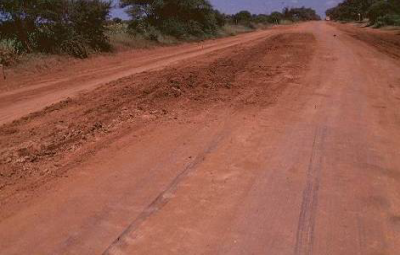
Figure 67. Photo. Very wide road.
Optimizing the road geometry is best considered during the design of new unpaved roads, but very few of these are being constructed at present. In most instances, very little can be done about improving the geometry of existing city, county, and state unpaved roads and roads on federal lands because of property ownership and/or environmental issues (for example removal of trees and rehabilitating the old roadway). However, small improvements where feasible and appropriate can have a positive impact on safety, road performance, and on reducing road management costs including the number of grader passes and the amount and frequency of regravelling.
In some instances, the width of very wide roads (usually caused over time by blading material from the sides of the road onto the crown [Figure 67]) can be reduced by reworking the shape and moving the side drains (consider re-vegetating the reclaimed areas). This will improve overall road shape, minimize the potential for pothole formation, and reduce maintenance requirements (number of grader passes required). Small changes can also be made to reduce the severity of sharp curves (Figure 68) by providing a super- elevation, and some widening of very narrow roads may be possible with land owner agreement. Improving a road surface by better material selection and use of a chemical treatment will invariably result in increased vehicle speeds and additional signs may be required to warn motorists of sub-standard geometry. Road managers should use every opportunity to improve road geometry where feasible to improve road safety and increase maintenance productivity. Maintenance issues are often related to poor geometry (for example, raveling on sharp curves, erosion on steep grades and super-elevations, water ponding in dips, etc.). Guidance on road geometry is available in the American Association of State Highway and Transportation Officials (AASHTO) Guidelines for Geometric Design of Very Low-Volume Local Roads (ADT ≤ 400) and the FHWA/South Dakota LTAP Gravel Roads Maintenance and Design Manual. When using chemical treatments on wider roads or roads with shoulders, apply to the full width to prevent loose material from being sucked onto the treated surface by moving vehicles and because shoulders will occasionally be subjected to traffic and water flow (Figure 69).
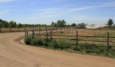
Figure 68. Photo. Very sharp curve.
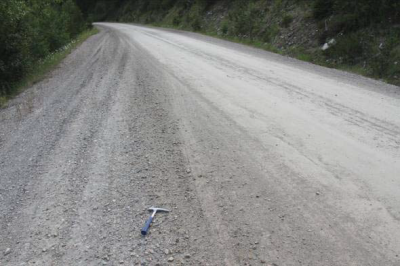
Figure 69. Photo. Untreated shoulder.
Additive applications at the end of the rain season are usually the most effective. Do not apply additives if rain, strong winds, or hot and dry conditions are imminent.
Prior to working on the roadway, insure that appropriate traffic control and safety devices are in place to inform the driver on what to expect ahead. These devices need to be installed in accordance with all of the agencies requirements, which may include the Manual of Uniform Traffic Control (MUTCD) requirements for Workzone Traffic Control.
Take appropriate safety precautions during application based on the recommendations in the vendor's guidance document and in the Material Safety Data Sheet (MSDS). Take care to ensure that the application is restricted to the road surface and that there is no runoff. Any chemical ending up off of the traveled way, in drains or on roadside vegetation is a reduction in both the application rate and potential effectiveness of the program and could have undesirable impacts on vegetation and surface water.
Road Closures
Always follow the supplier's recommendations for applying the chemical treatment. Some treatments (e.g., synthetic polymer emulsions, organic petroleums and petroleum resins) may require a road closure while the product is applied and for the duration of curing (typically 15 minutes to two hours). Even when not required by the supplier, where possible, ask the road users to wait at the start of the section until spraying is complete. This will limit unsafe driving conditions and reduce product adhering to vehicles.
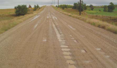
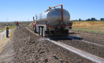
Application rates depend on a number of factors including whether it is an initial application or a periodic rejuvenation, material properties, traffic volume and speeds, and climate. Always follow the supplier's recommendations. Avoid dilution of the products themselves beyond the manufacturer's recommended values since excessively diluted applications will not survive or remain in service as well or as long, will be subject to more rapid degradation (Figure 70) and runoff during rainfall events and, even when freshly applied, may not control fines or dust effectively when compared to the recommended dilution.
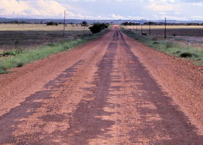
Figure 70. Photo. Insufficient additive application.
In some cases, a residual build-up of the product in the roadway will provide an opportunity to reduce the reapplication rates and still restore the road to its original full first-application performance. The product supplier should have researched application rates in detail and should provide guidance in the form of charts along with the chemical. If they cannot, it means that the road manager will be doing research on their behalf and consequently any performance claims that the supplier has made should be considered with care. No recommendations on specific products' application rates are made in this handbook.
For spray-on applications, always follow the supplier's recommendations, but consider the following:
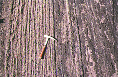
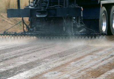
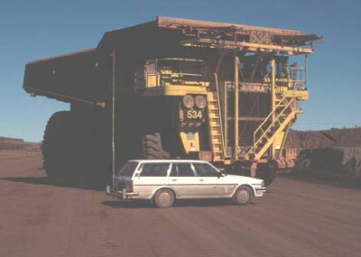
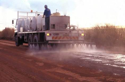
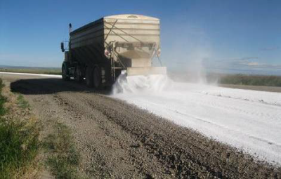
Figure 75. Photo. Flake application of calcium chloride.
Calcium and magnesium chloride can also be applied in flake or pellet form (Figure 75). These can either be dissolved in a water tanker and
sprayed on to the road as discussed above. Beware that this is an exothermic reaction and significant and possibly dangerous temperatures may be reached depending on the dilution ratio.
Alternatively, they can simply be spread onto the road surface. Always follow the manufacturer's recommendations, but consider the following for applications by spreading:
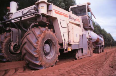
A mix-in process will typically provide effective dust abatement and/or gravel retention for longer periods than spray-on applications. The additional costs incurred during construction will usually be offset by extended rejuvenation intervals, by improved performance, and by less frequent road maintenance. Mixing depths will depend on the type of chemical treatment being used and the purpose of the treatment. For dust control treatments, mixing depth is typically one to two inches (25 mm to 50 mm). For soil stabilization treatments, mixing depth is typically four to six inches (100 mm to 150 mm) depending on the thickness of the layer, the type of additive used, truck traffic, and the purpose of the application. Clay stabilization and applications to improve all-weather passability on roads with high volumes of truck traffic are usually deeper.
For mix-in treatments, consider the following:
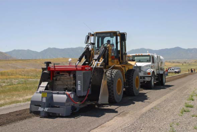
Figure 76. Photo. Equipment-mounted recycler.
It's worth repeating that compaction is key to getting a tight road surface of the proper shape that will shed water and resist traffic loads. If the procedures above cannot be followed, or if the recommended equipment is not available, expect reduced performance of the product. It's always a good idea to close the road to traffic until the final application has penetrated into the road surface to prevent vehicles from picking up the additive.
If new gravel is imported as part of the chemical treatment program, care must be taken to ensure that it meets the required specification (see discussion in Chapter 5) and that it is placed to the best possible construction standard. Detailed guidance on construction is beyond the scope of this handbook, but key processes include:
To protect your investment and record the improvements, it makes sense to conduct periodic drive-by inspections to evaluate the short-term and long-term effectiveness of the applications. After the application has cured, observe how the road surfaces respond to traffic and survey road users and adjacent land owners. Determine acceptable levels of dust reduction (an 80 to 90 percent reduction in dust levels compared to those on an untreated road will satisfy most road users and is often much cheaper than trying to achieve 100 percent dust control). Figure 82 through Figure 85 provide a guide for evaluating the effectiveness of dust control treatments.
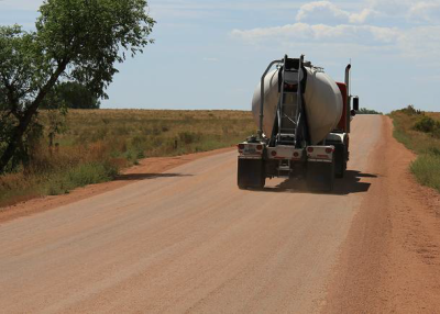
Figure 82. Photo. No dust. (1 on a scale of 1-5).
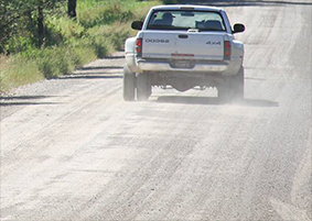
Figure 83. Photo. Acceptable level of dust. (2 on a scale of 1-5).
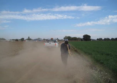
Figure 84. Photo. Average level of dust. (3 on a scale of 1-5).
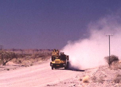
Figure 85. Photo. Unacceptable level of dust. (5 on scale of 1-5).
Use photographs from your roads to refine the evaluation process. Make arrangements to evaluate dust levels, gravel loss (using a dynamic cone penetrometer [Figure 86], by digging holes to measure layer thickness [Figure 87], or measuring stone protrusion [Figure 88], assuming that the tops of stones were level with the road surface after construction), shape retention (using a level, Figure 89), and ride quality.
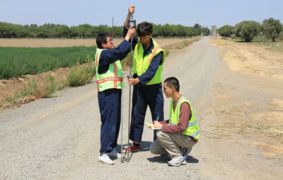
Figure 86. Photo. Checking layer depths with dynamic cone penetrometer.
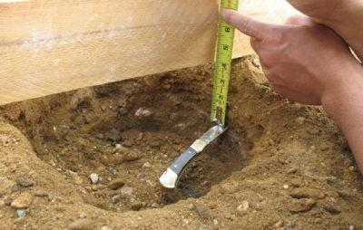
Figure 87. Photo. Checking gravel thickness.
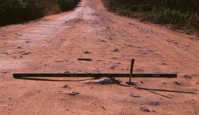
Figure 88. Photo. Estimating gravel loss from stone protrusion.
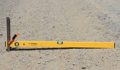
Figure 89. Photo. Checking crown with a simple level.
Document your observations on an appropriate form (examples in Appendix B, visual assessment guideline available in Reference No 8) for easy reference at a later date and keep a photographic record of before and after images (Figures 90 and as a reminder of the level of improvement. This information will help determine if the treatment method and application rate are appropriate to meet the intended dust control objective and whether the exercise will result in program savings. Consider doing rejuvenations before dust levels are unacceptable as application rates will be much lower compared to later full- dose applications that will be needed. Most products will build up a residual level over time and application rates will be reduced and rejuvenation intervals will increase over time, thereby reducing annual maintenance costs. Use this information to prove to your Managers/ Supervisors/Employers/ Governing Boards/ Commissioners and road users that the dust control program is cost effective.
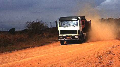
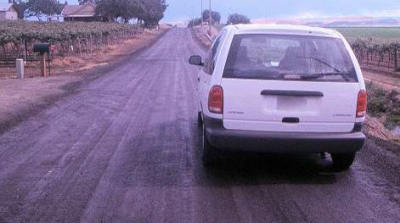
Figure 90. Photo. Road before treatment.
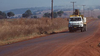
Figure 91. Photo. Road after treatment.
Stay up to date
Sign up for announcements on grant opportunities, training, and webinars.